


Z-Beam Load Cell | S-Beam Load Cell | High Accuracy | DBB
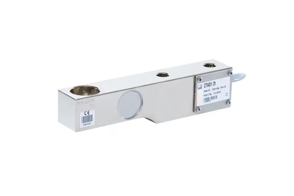
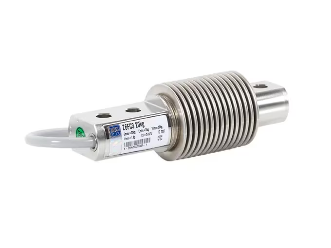
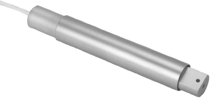
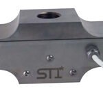
Applied Measurements DBB Z-beam load cell / S-beam load cell is suitable for use in tension or compression with IP67 immersion protection to 1m. The design lends itself to both force and load measurement applications such as those found on tensile testing machines, suspended hoppers and geotechnical test equipment, as well as a wide range of other general-purpose applications. The sensing principle employed on our Z-Beam load cell varies, with a dual bending beam design on the DBBE model which covers capacities from 50kg up to 1000kg and a shear web design on the DBBWAS model which cover ranges from 0-1500kg to 0-6000kg. Both sensing principles offer inherently high accuracy and enable us to guarantee performance of better than ±0.05% of rated capacity. All our DBB models are constructed from nickel-plated alloy steel. Rod end bearings and load buttons are available (see gallery images) to provide optimum loading conditions. If you require a Z-Beam load cell with capacities of less than 50kg or greater than 6,000kg, Applied Measurements DBBSM series of S-Beam load cells covers load ranges from 0-1kg (10N) up to 0-30,000kg (300kN). Meanwhile, if you need to fit into a restricted space, our DBBSMM range of miniature S-Beam load cells will fit the bill.
Technical Specifications
| DBBE | DBBWAS | Units | |
|---|---|---|---|
| Rated Capacity (RC) | 0-50, 0-100, 0-150, 0-200, 0-300, 0-500, 0-1000 | 0-1500, 0-2000, 0-3000, 0-5000, 0-6000 | kg |
| Operating Modes | Tension/Compression/Tension & Compression | ||
| Sensitivity (RO) | 2.0 ±0.1% | mV/V | |
| Zero Balance/Offset | <0.2 | ±mV/V | |
| Total Error | <0.05 | ±%/Rated Output | |
| Zero Return after 30 mins | <0.05 | ±%/Applied Load | |
| Output Symmetry (tension vs. compression) | <0.2 typical | ±%/Rated Output | |
| Temperature Effect on Zero | <0.01 | ±%/Rated Load/˚C | |
| Temperature Effect on Sensitivity | <0.003 | ±%/Applied Load/˚C | |
| Input Resistance | 400 ±20 | Ohms | |
| Output Resistance | 350 ±3 | Ohms | |
| Insulation Resistance | >2000 | Megohms | |
| Excitation Voltage | 10 recommended (2-15 acceptable) | Volts AC or DC | |
| Operating Temperature Range | -30 to +70 | ˚C | |
| Compensated Temperature Range | -10 to +40 | ˚C | |
| Storage Temperature Range | -30 to +70 | ˚C | |
| Safe Overload | 150 | % of Rated Capacity | |
| Ultimate Overload | 300 | % of Rated Capacity | |
| Deflection @ Rated Capacity | <0.4 | mm | |
| Fundamental Resonant Frequency* | 200 to 1000 typical depending on capacity | Hz | |
| IP Rating (Environmental Protection) | IP67 | ||
| Weight (excluding cable) | 0.7 | kg | |
| Fatigue Life | Consult Sales | ||
| Cable Length (as standard) | 6 | metres | |
| Cable Type | 6-core screened, PUR sheath, Ø6.3 | ||
| Construction | Nickel Plated Alloy Steel | ||
| Resolution: | 1 part in 250,000 (with appropriate instrumentation) | ||
| *The resonant frequency is calculated with the body of the load cell attached to a large plate, ensuring that only the sensing element oscillates: This is vital to achieve the highest natural frequency and subsequent frequency response. | |||
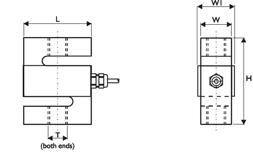
Product Dimensions
|
Model
|
Capacity (kgf)
|
H
|
L
|
W
|
W1 (nom)
|
H1
|
Threads T
|
|---|---|---|---|---|---|---|---|
|
DBBE
|
0-50 to 0-1000
|
80
|
62.1
|
18
|
22
|
15
|
M12 x 1.75
|
|
DBBWAS
|
0-1500, 0-2000
|
90
|
70
|
32
|
36
|
19
|
M16 x 2.0
|
|
DBBWAS
|
0-3000, 0-5000, 0-6000
|
120
|
100
|
45
|
45
|
26
|
M24 x 2.0
|
All dimensions are in mm
Wiring Details
| Wire | Designation |
|---|---|
| Red | +ve excitation |
| Black | +ve sense |
| Blue | -ve excitation |
| White | -ve sense |
| Green | +ve signal (tension) |
| Yellow | -ve signal |
VA24
Ordering Codes & Options
| Core Product | Capacity (inc Engineering Units) | Cable Length (m) | Specials Code | Example Result |
|---|---|---|---|---|
| DBBE | 50kg | 006 | 000 | DBBE-50kg-006-000 |
| DBBE | 100kg | 006 | 000 | DBBE-100kg-006-000 |
| DBBE | 150kg | 006 | 000 | DBBE-150kg-006-000 |
| DBBE | 200kg | 006 | 000 | DBBE-200kg-006-000 |
| DBBE | 300kg | 006 | 000 | DBBE-300kg-006-000 |
| DBBE | 500kg | 006 | 000 | DBBE-500kg-006-000 |
| DBBE | 750kg | 006 | 000 | DBBE-750kg-006-000 |
| DBBE | 1000kg | 006 | 000 | DBBE-1000kg-006-000 |
| DBBWAS | 1500kg | 006 | 000 | DBBWAS-1500kg-006-000 |
| DBBWAS | 2000kg | 006 | 000 | DBBWAS-2000kg-006-000 |
| DBBWAS | 3000kg | 006 | 000 | DBBWAS-3000kg-006-000 |
| DBBWAS | 5000kg | 006 | 000 | DBBWAS-5000kg-006-000 |
| DBBWAS | 6000kg | 006 | 000 | DBBWAS-6000kg-006-000 |
Mounting and Installation Accessories
Load Buttons and Rod End Bearings
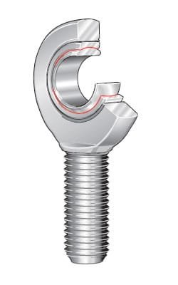
Designed to align forces through the principle axis of the load cell thus reducing the effects of extraneous forces, hence offering improved performance from the cell. Load buttons are used where compressive forces are applied. Rod End Bearings are used where tensile forces are being applied.
Load Buttons for Compression Use
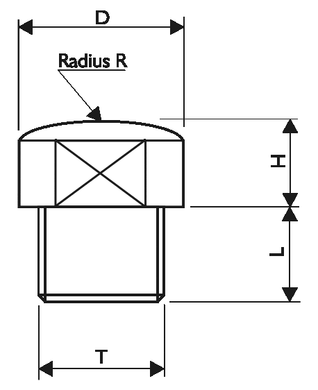
| THREAD T | M12 x 1.75 | M16 x 2 | M24 x 2 |
|---|---|---|---|
| D | 22 | 32 | 26 |
| H | 6 | 10 | 14 |
| L | 12 | 16 | 26 |
| R | 150 | 180 | 200 |
Rod End Bearings for Tension Use
- Supports radial loads in a tensile or compressive direction.
- Transmit slow movements with small or moderate swivel angles.
- Suitable for unilateral loads – can support alternating loads and alternating loads in combination with bearing GE..UK-2RS.
- Zinc plated for corrosion resistance.
- Are maintenance-free.
- Sealed maintenance-free rod ends use lip seals to protect against contaminants and water spray.
- Fitted with radial spherical plain bearings GE..UK
- Hard chromium/PTFE composite sliding contact surfaces.
- Right hand or left hand internal or external thread.
- Enables compact adjacent construction thanks to its thin walled design of the eye housing.
GAR..UK (right hand thread) GAL..UK (left hand thread) To ISO 12 240-4, dimension series E, type M Shank with external thread For shaft diameters from 6mm to 30mm Maintenance-free ISO 12 240-4, dimension series E, type M Sliding contact surface: hard chromium/PTFE Series GAR..UK Sliding material: PTFE composite

| TYPE | SHAFT DIAMETER | DESIGNATION 1) | MASS | DIMENSIONS | |||||||
|---|---|---|---|---|---|---|---|---|---|---|---|
| d | WITHOUT SEALS | WITH SEALS | ≈ kg | d | D | B | dK | d1 | d2 | d3 | |
| DBBE-50-1000kg | 12 | GAR 12 UK | — | 0.086 | 12-0.008 | 22 | 10-0.12 | 18 | 14.9 | 34 | M12 |
| DBBWAS-1500-2000kg | 17 | GAR 17 UK | — | 0.19 | 17-0.008 | 30 | 14-0.12 | 25 | 20.7 | 46 | M16 |
| DBBWAS-3000-6000kg | 25 | GAR 25 UK | — | 0.56 | 25-0.01 | 42 | 20-0.12 | 35.5 | 29.3 | 64 | M24 x 2 |
| TYPE | Degrees | Chamfer Dimension | Basic Load Ratings | Radial Internal Clearance | Shaft Diameter | ||||||
|---|---|---|---|---|---|---|---|---|---|---|---|
| h | C1 | α | l1 | l2 | l7 | r1s min. | dyn. Cr N | stat. C0r N | d | ||
| DBBE-50-500kg | 54 | 8 | 11 | 28 | 71 | 18 | 0.3 | 11 400 | 30 100 | 0 — 0.032 | 12 |
| DBBW-1500-2000kg | 69 | 11 | 10 | 36 | 92 | 23 | 0.3 | 22 400 | 56 500 | 0 — 0.04 | 17 |
| DBBW-3000-6000kg | 94 | 17 | 7 | 53 | 126 | 32 | 0.6 | 51 000 | 104 000 | 0 — 0.05 | 25 |
| 1) For a left hand thread, the R is replaced by an L (example: GAL..). | |||||||||||