


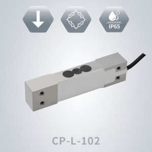
A cantilever beam load cell consists of an elastic body, strain gauges, and measurement circuitry. Cantilever beam sensors typically employ a single-end fixed configuration, where one end is rigidly fixed while the other end is freely suspended. Unlike parallel beam sensors, the strain gauges for cantilever beam sensors need to be affixed closer to the fixed end, whereas those for parallel beam sensors are attached to the top and bottom surfaces of the two beams. The working principle of load cells can be referenced from the introduction of CP series load cells.
Our company’s CBD series digital cantilever load cell is a digital sensor that comes with a high-precision analog-to-digital conversion module, allowing it to output digital signals rather than analog ones. Compared to analog sensors, digital sensors have the following advantages:
1. Digital signals have stronger interference resistance;
2. They support various compensation functions, such as temperature compensation and load offset compensation;
3. Communication speed is significantly improved compared to analog signals.
The CBD series digital load cells offer a wide measurement range from 220 kg to 4400 kg, with an accuracy class up to C6 level. Additionally, they feature IP68/IP69K protection ratings, providing better protective performance in industrial production environments.
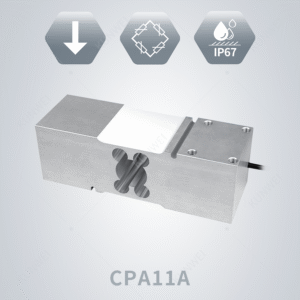
Parallel beam sensors mainly consist of an elastic body, strain gauges, and measurement circuits. The elastic body of parallel beam sensors uses a dual parallel beam structure, typically made from aluminum alloy or stainless steel. When the elastic body deforms under external force, the strain gauges attached to its surface also deform, causing changes in their resistance values. These changes in resistance values are converted into electrical signals through the measurement circuit and then transformed into readable weighing values via an analog-to-digital converter (ADC module). Parallel beam sensors, known for their simple structure, high precision, wide measurement range, and good stability, have become one of the most commonly used types of load sensors in industrial fields, especially suitable for high-precision measurement scenarios.
Our company’s CP series parallel beam load cells are high-performance single-point load cells with a measurement range of 3 kg to 750 kg, available in multiple size specifications. The product has obtained the China Measuring Instruments Type Approval Certificate (CPA) and achieves precision levels of C5/C6, with repeatability error ≤ ±0.01 F.S., meeting customers’ precision requirements across different weighing ranges. The operating temperature of the product is -30°C to +65°C, with an IP67 protection rating. It features automatic corner adjustment, compact design, and temperature compensation, significantly enhancing its accuracy and stability when used in industrial environments. Due to its excellent performance, the CP series load cells are widely used in various industrial and retail weighing applications such as electronic price scales, packaging scales, and process weighing control systems.
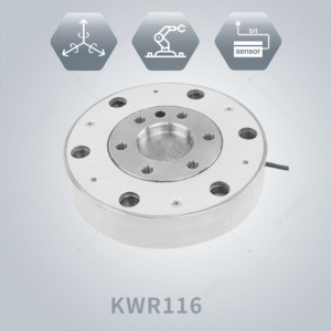
KWR116 series is designed specifically for industrial robotic applications. The series provides a wide range of force and torque capacities to select from. It has various versions for different requirements.The built-in high-precision data acquisition module can combine with the six-axis joint decoupling algorithm to achieve higher accuracy and precision of the sensor.
KWR116 series is designed specifically for industrial robotic applications. The series provides a wide range of force and torque capacities to select from. It has various versions for different requirements.The built-in high-precision data acquisition module can combine with the six-axis joint decoupling algorithm to achieve higher accuracy and precision of the sensor.
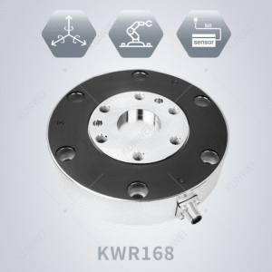
The KWR168 series is a six axis force sensor with a large range, capable of carrying a force of 8000N. It is generally used at the end of industrial robots and meets the needs of most industrial robotic arms.

KWR200 series six-axis torque sensor is a large torque range and embedded six-axis force sensor with higher accuracy and precision , which can be applied to the base sensor of cooperative robots and also meet the use needs of most industrial mechanical arms. This transducer is widely used in building model wind load test, medical testing, automobile testing, 3C testing, industrial automation, scientific research and other industries.
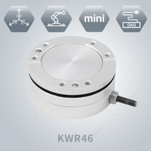
The KWR46 series sensor is a small-size compact six-axis force sensor. It has characristics with light weight and small volumn. Its measuring range is around 50N to 200N, and could be customized as your needs. Our product has high anti-overload protection ability, it can withstand 300% overload.The small-size sensor widely used in scientific research and medical testing fields. For this series model small volumn that it can’t be embedded in circuit board moduel, so we will provide a signal acquisition box according to the communication protocol version you need.
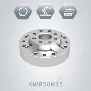
KWR50N15 torque sensor is a high-precision product that can achieve direct quantity output in both analog and digital formats. The main dimensional parameters are an outer diameter of 50mm, an inner diameter of 12mm, a height of 17mm, and a measurement range of 15N · m. Suitable for fields such as robot joints, collaborative robotic arms, and precision medical equipment, precise measurement and control of torque is a key link in ensuring equipment performance, improving production efficiency, and ensuring safe operation. The KWR50N15 torque sensor, with advanced measurement technology and reliable design, accurately senses and outputs torque signals, providing strong support for various torque monitoring devices.
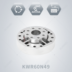
Torque sensor (KWR60N49)is a high-precision product that uses digital output. The outer diameter of this product is 60mm, the height is 21mm, and it works at the rated range of 49 Nm. Its accuracy can reach at least 0.5% F.S., and its nonlinear and hysteresis performance can be controlled within the accuracy range. In addition, after finite element analysis and verification, the sensor can withstand a lateral ultimate bending moment of 60 Nm, and its strong lateral torsional bearing capacity ensures stability under normal use. The torsional stiffness is maintained within 57 kNm/Rad, and the maximum torsional angle does not exceed 0.04 °. The axial ultimate load of 2 kN and the lateral ultimate load of 3 kN perform equally well. The excellent compressive and tensile performance lays a solid foundation for the digital signal output of the product in the direction of the rated torsional moment, thereby demonstrating outstanding performance. The sensor can operate within a wide temperature range of -10~80 ℃, with a temperature span of up to 90 ℃. Even in extremely harsh temperature environments, our sensor can maintain excellent performance. The product design is based on a solid theoretical foundation, and the test results have extremely high credibility.
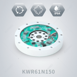
KWR61N150 Joint Torque Sensor is a high-precision product that uses RS485 communication output and 5V DC power supply. This product has an outer diameter of Φ 61mm and a height of 17.5mm, including the height of the built-in PCBA circuit board and the height of the fixing screws. When selecting products, it is often necessary to calculate the force situation of joints in the robot system to ensure that the torque sensor matches the joint torque parameters in the design, so that the torque is within the linear detection range. The detection range for repeatability, nonlinearity, and hys。teresis of this product is within 0.5% F.S. The torque borne by the joint can be expressed through a specific formula. After calculating the maximum torque borne by the joint, it can be used as a selection basis for sensor range and overload resistance. This product has a range of 150Nm and can withstand 200% safe overload and 300% ultimate destructive load. In addition, when subjected to lateral torsional loads, the maximum rated bending moment of the sensor is 110 Nm, the torsional stiffness is maintained within 214 kNm/Rad, and the maximum torsional angle does not exceed 0.04 °. When the sensor is subjected to lateral load, the maximum rated load is 14.42kN; in the direction of the sensor bearing axis, the rated load limit is 9.61 kN. The applicable working temperature range of this product is between -10 ℃ and 80 ℃, which can better adapt the torque sensor to various complex environments.

The KWR61N150 series is a small size, large range torque sensor designed with a special structure, specifically designed to measure the torque at the output end of the joint reducer of the robotic arm. It is conducive to decoupling the dynamic model of the robotic arm, performing position control based on dynamics, and achieving force control.
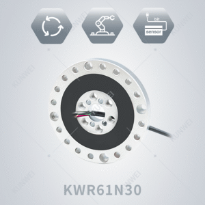
KWR61N30 torque sensor is a high-precision product that can output both analog and digital signals directly. This product can customize and adapt high-precision signal acquisition modules according to different signal output requirements (such as RS485, CAN signal output). The product has an outer diameter of Φ 61mm and a height of 10mm. At a rated range of 30Nm, its repeatability, nonlinearity, and hysteresis performance can be controlled within the range of 0.5% F.S. When subjected to lateral torsional loads, the maximum rated bending moment of the sensor is 20 Nm, the torsional stiffness is maintained within 57 kNm/Rad, and the maximum torsional angle does not exceed 0.04 °. When the sensor is subjected to lateral loads, the maximum load rating is 4.2 kN; in the direction of the sensor bearing axis, the load limit rating is 2.5 kN. If the lateral ultimate bending moment, lateral ultimate load, or axial ultimate load exceeds these ratings, the sensor structure will face the risk of damage or instability. The applicable working temperature range of this product is between -10 ℃ and 80 ℃. Within this temperature range, the output of the sensor can remain stable and not be affected by temperature fluctuations. Beyond the temperature range, stability may be affected and the output signal may drift or fluctuate. This product has been verified through multiple practical tests, and the theoretical data is highly consistent with the actual data, demonstrating superior performance.

KWR61N66 series torque sensor is designed for measuring the torque value of robot joint. It has unique design with disc deign, low height and double flange structure, to provide enough installation stength and stiffness.
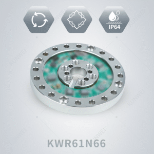
KWR61N66 Joint Torque Sensor is a high-precision product powered by 9~24V DC and outputting digital signal RS485. The wiring method is that the red line corresponds to positive power supply, the black line corresponds to negative power supply, the green line corresponds to 485A+, and the white line corresponds to 485B -. In addition, this product can also output 0-10V, with the red line corresponding to positive power supply, the black line corresponding to negative power supply, the green line corresponding to positive signal, and the white line corresponding to negative signal. The outer diameter of this product is Φ 61mm, with a total height of 10mm, including the height of the built-in circuit board. For the production calibration testing of joint torque sensors, the calibration experimental measurement system includes a high-precision six and a half position instrument, a DC stabilized power supply, a calibration table, and weights. The elastic body is connected to the PCB, and torque calibration is performed by adding weights to the lever connected to the torque measurement sensor, thereby accurately fitting the torque coefficient of the joint. The range of this product is 66Nm, and the detection range of repeatability, nonlinearity, and hysteresis is within 0.5% F.S. It can withstand 200% safe overload and 300% ultimate load. In addition, when subjected to lateral torsional loads, the maximum lateral ultimate bending moment of this product is 66Nm, the torsional stiffness is within 25.4kNm/Rad, and the maximum torsional angle does not exceed 0.03 °. The lateral ultimate load of the sensor is 11.5kN; the axial load limit is 6.39 kN. The applicable working temperature range of this product is between -10 ℃ and 80 ℃, and it can adapt to various complex environments.