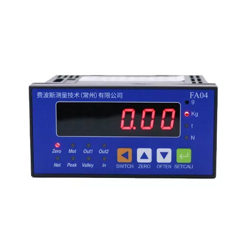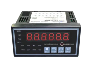


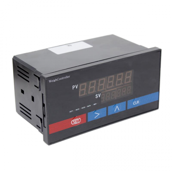
ZM300 220V LED 6 digit weight indicator

1.Introduction:
The display uses a 24 bit A / D converter, can be connected to various types of sensors and transmitters to achieve the pressure, flow, level, composition analysis and volume measurements, and other physical and mechanical parameters, display, alarm monitoring, data acquisition and recording.
2.Parameters:
| Work Environment: | Temperature:-20-50℃ | Display | Dual 5 high brightness red LED |
| Humidity:20-90%RH | Output excitation voltage | 5V ~15V (for sensor supply), current <50MA | |
| Accuracy | ±0.2%F.S±1 word | Supply Voltage | AC195 ~ 242V, power consumption <5w |
| Monitoring cycle | 0.2 seconds: can be increased to 0.05 seconds |
3.Button introduction:
“SET”button:SET “>”button:Shift key or tare key(peak meter)
“∧”button:UP “CLR”button:Peak clear key or tare key(upper and lower limit gauge)
- Content:
| Symbol | Name | Range |
| SAL | OUT1relay | 00000~full scale |
| SPL | OUT1deviation | 0<SPL<SAL |
| SAH | OUT2relay | 00000~full scale |
| SPH | OUT2deviation | 0<SPH<SAL |
| SL | Zero calibration | 00000 |
| SH | Load calibration | More than half scale |
| Sd | Decimal location | 0~3 |
| Id | Division value | 1.2.5.10.20 |
| CLTF | Peel key selection | 0.1 |
| FIL | Weight filtering degree | 1-9 |
| ZERO | Zero tracking range | 0~4 |
| bd | Baud rate | 0~3 |
| Ad | Address setting(RS485 only) | 01-30 |
| OUTF | Alarming output | 0 or 1 |
- Operating introduction:
1. Press’SET’ more than three seconds to show ‘SAL’for setting OUT1relay. Press’SET’ again to show ‘SPL’ for setting OUT1deivation Explanation: When ‘SPL’=0, if force value > SAL, OUT1 close; If force value < SAL, OUT release When ‘SPL’≠0, if force value > SAL+SPL, OUT1 close; If force value < SAL+SPL, OUT1 release
2. Press’SET’ to show ‘SAH’for setting OUT1relay. Press’SET’ again to show ‘SPH’ for setting OUT2deivation
3. Press’SET’ to show ‘CIN’ for entering password. The original password is 00000. If you don ’t want to change password, press ‘SET’ for next step. If you want to change password, press ‘CLR’ to show ‘CON’, set your 5 digit password and press ‘SET’ for next step.
4. Press ‘ SET’ to show ‘SL’ for zero calibration
5. Press’SET ’to show ‘SH’ for load calibration. The loading should be more than half scale. Input corresponding force value.
6. Press’SET’ to show ‘Sd’ for decimal setting. Press ‘∧’ for adjusting decimal location.
7. Press’SET’ to show ‘Id’ for division value.
8. Press’SET’ to show ‘CLFT’ for peel key selection. When ‘CLFT’ is 0, ‘CLR’ can peel. When ‘CLFT’ is 1, ‘CLR’ cann’t peel.
9. Press ‘SET’ to show ‘FIL’ for weight filtering. The value is from 1-9. The value means the speed of value stability. The bigger the value is, the slower the speed stabilize.
10. Press ‘SET’ to show ‘ZERO’, if the time is less than 2 seconds, the value will track to zero.
- Communication protocol
- Baud rate
| bd | Value | Baud rate |
| 0 | 2400 | |
| 1 | 4800 | |
| 2 | 9600 | |
| 3 | 19200 |
- RS232 wiring definition
Serial ports are GND(indicator 21 foot), RXD(indicator 22 foot), TXD(indicator 23 foot), RXD refers to PC’s RXD. TXD refers to PC’s TXD.
- Communication adopts MODBUS-RTU format: address domain+functional domain+data domain+check domain
Functional domain:
| Functional code | meaning | Behavior |
| 0x03 | Read data register | Read data register value |
| 0x10 | Modify data register | Overwrite multi-bit data register values |
Format:
Read data register
| address | function | Data
start reg hi |
Data
start reg lo |
Data # of
Reg hi |
Data # of
Reg lo |
Crc-16 lo | Crc-16 hi |
| 0x01 | 0x03 | 0x00 | 0x55 | 0x00 | 0x01 | 0x94 | 0x1A |
Modify the switch
| address | function | Data
start reg hi |
Data
start reg lo |
Data # of
Reg hi |
Data # of
Reg lo |
Crc-16 lo | Crc-16 hi |
| 0x01 | 0x05 | 0x00 | 0x00 | 0xFF | 0x00 | CRC0 | CRC1 |
Modify data register
| address | function | Data
start reg hi |
Data
start reg lo |
Data # of
Reg hi |
Data # of
Reg lo |
Byte
count |
Value hi | Value
lo |
Crc-16 lo | Crc-16 hi |
| 0x01 | 0x10 | 0x00 | 0x50 | 0x00 | 0x01 | 0x02 | 0x03 | 0xE8 | 0xAA | 0xBE |
Address: Follower address function: function code
Data start reg hi: Register start address high byte Data start reg lo: Register start address low byte
Data # 0f reg hi: Read register number high byte Data # 0f reg lo: Read register number low byte
Crc -16 lo: Check code low byte Crc -16 hi: Check code high byte
- Parameters and address
Register addressParametersValue rangeData type 0x50LO limit0-60000word 0x51LO deviation0-60000word 0x52UPPER limit0-60000word 0x53UPPER deviation0-60000word 0x54Decimal0-3word 0x55Positive or negative0 is positive ; 1 is negativeword 0x56Value display0-60000word0x57peelWrite 1 means peelword
- Attention
1. Setting error or invalid, press’∧’ for reset.
Press’>’ for three seconds to display 0 or 1. Press ‘>’ again for switching 0 and 1. When display ‘0’ press’>’ for lowest force value indicator, when display ‘1’ for peak indicator.