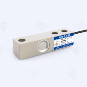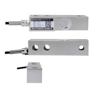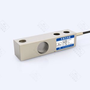


Shear Beam Load Cell | OSBST
Accurate, Robust and IP68-Rated for Tough Weighing Applications. Applied Measurements OSBST single-ended shear beam load cell is suitable for medium capacity weighing applications such as hoppers and vessels where a highly accurate measurement system is required. They are also suitable for conveyor weighing applications. The high integrity IP68 body and stainless steel construction of the OSBST single-ended shear beam load cell means that it is ideal for use in process situations where regular washdowns are required to maintain hygiene standards. Two mounting assemblies are available to suit Applied Measurements OSBST, the Vessel Mount for static applications and the Shock / Anti-Vibration Mount for mixer, feed hopper and conveyor applications where vibration or transient loads may occur. For mount dimensions, please download the datasheet. For hazardous environments, the OSBST single-ended shear beam load cell is available with ATEX (EEx ia IIC T6) hazardous area approvals. Third party products like the SB14 can be easily substituted by our OSBST product and will deliver similar performance and longevity.
Technical Specifications
| OSBKT | OSBST | UNITS | |
|---|---|---|---|
| Rated Capacity (RC) | 0-250, 0-500, 0-1000, 0-2000 | 0-500, 0-1000, 0-2000, 0-5000 | kgf |
| Operating Modes | Compression Only | ||
| Sensitivity (RO) | 2.0 ±0.1% | mV/V | |
| Zero Balance/Offset | <2.0 | ±%/Rated Output | |
| Zero Return after 30 mins. | <0.025 | ±%/Rated Capacity | |
| Accuracy | <0.020 | ±%/Rated Capacity | |
| Temperature Effect on Zero | <0.0023 | ±%/Rated Output/ ˚C | |
| Temperature Effect on Sensitivity | <0.0010 | ±%/Applied Load/ ˚C | |
| Input Resistance | 380 nominal | Ohms | |
| Output Resistance | 350 nominal | Ohms | |
| Insulation Resistance | >2000@50Vdc | Megohms | |
| Excitation Voltage | 10 recommended (2-15 acceptable) | Volts AC or DC | |
| Operating Temperature Range | -20 to +70 | ˚C | |
| Compensated Temperature Range | -10 to +40 | ˚C | |
| Storage Temperature Range | -20 to +70 | ˚C | |
| Safe Overload | 150 | % of Rated Capacity | |
| Ultimate Overload | 300 | % of Rated Capacity | |
| Deflection @ Rated Load | <0.4 | mm | |
| IP Rating (Environmental Protection) | IP67 | IP68 | |
| Weight (excluding cable) | 0.9 (250kg, 500kg & 1000kg), 1.1 (2000kg), 2.1 (5000kg) | 0.9 (500kg, 1000kg & 2000kg), 1.9 (5000kg) | kg |
| Fatigue Life | 108 cycles typical (109 cycles on fatigue-rated version) | ||
| Cable Length (as standard) | 3 | 5 | metres |
| Cable Type | 6 core screened, PUR sheath, Ø6mm | ||
| Construction | Nickel Plated Alloy Steel | Stainless Steel | |
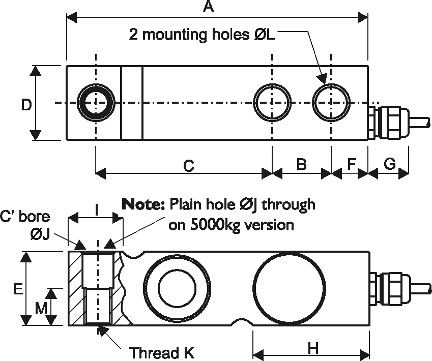
Product Dimensions
|
Model
|
Capacity (kg)
|
A
|
B
|
C
|
D
|
E
|
F
|
G
|
H
|
I
|
ØJ
|
K
|
ØL
|
M
|
|---|---|---|---|---|---|---|---|---|---|---|---|---|---|---|
|
OSBST
|
500, 1000, 2000
|
130
|
25.4
|
76.2
|
32
|
32
|
15.8
|
18
|
50.5
|
23.5
|
13.5
|
M12 x 1.75
|
13.5
|
16
|
|
OSBST
|
5000
|
171.5
|
38.1
|
95.25
|
36.5
|
48
|
19
|
18
|
70
|
37
|
20.5
|
M20 x 2.5
|
20.5
|
—
|
All dimensions are in mm
Wiring Details
| Wire | Designation |
|---|---|
| Blue | +ve excitation |
| Green | +ve sense |
| White | +ve signal |
| Black | -ve Excitation |
| Grey | -ve Sense |
| Red | -ve Signal |
| Screen | To ground – not connected to load cell body |
Ordering Codes & Options
| Core Product | Capacity (inc Engineering Units) | Cable Length (m) | Specials Code | Example Result |
|---|---|---|---|---|
| OSBST | 500kg | 005 | 000 | OSBST-500kg-005-000 |
| OSBST | 1000kg | 005 | 000 | OSBST-1000kg-005-000 |
| OSBST | 2000kg | 005 | 000 | OSBST-2000kg-005-000 |
| OSBST | 5000kg | 005 | 000 | OSBST-5000kg-005-000 |
Mounting Accessories
VESSEL MOUNT ASSEMBLY
- Simple to Install Into New or Existing Installations.
- Can be Installed With or Without the Load Cells in Position
- Stainless Steel Construction
- Easy Lifting and Removal of Load Cell
- Rugged Construction
- Reduces Installation Time
- Permanent Integral Safety Vessel Jacking System for your Vessel
- Anti-Lift Mechanism for Greater Vessel Stability
- Maximum Safety Protection from the Effects of Wind or Accidental Collision are Built-In.
- Heavy Duty Earth Straps Ensure that no Potential Difference Between the Upper and Lower Plates Occurs.
- Low Resistance Path Assists in Removing Strong Welding Currents.
- Substantial Protection Plate is Positioned Above the Cable Outlet to Prevent Damage by Falling Objects or Misuse.
| MODEL | OSBKT & OSBST 500-2000kg | OSBKT & OSBST 5000kg |
|---|---|---|
| A | 100 | 135 |
| B | 108 | 143 |
| C | 110 | 153 |
| D | 51 | 47 |
| E | 165 | 216 |
| F | 15 | 20 |
| G | 14 | 19.8 |
| H | 130 | 162 |
| I | 20 | 31.5 |
| J | 70 | 90 |
| K | 24 | 29 |
| L | 15 | 20 |
| M | M16 | M16 |
| N | 70 | 90 |
| O | 20 | 31.5 |
| P | 24 | 29 |
| Q | 111 | 159 |
SHOCK MOUNT ASSEMBLY
- Enables Weighing when a Vessel or Hopper is Subjected to External Forces
- Plated Steel Construction
- Minimises the Effects of Vibration
- Ease of Assembly Reduces Installation Time
- Complete Assembly is Supplied
| MODEL | OSBKT & OSBST 500-2000kg |
|---|---|
| A | 146 |
| B | 110 |
| C | 70 |
| D | 24 |
| E | 130 |
| F | 165 |
| G | 20 |
| H | 14 |
| I | 20 |
| L | 220 |
| M | 180 |
| N | 146 |
| O | 24 |
| P | 26 |
| Q | 18 |
| R | 106 |
| S | 30 |