

Rugged Compact Canister Compression Load Cell-Series CNR950
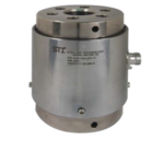
Standard for most sizes are welded on or Hermetic bolt on electrical connectors made of stainless steel.
Other features you can expect include a 5 point calibration record (NIST traceable) as well as vibration and shock protection.
DESCRIPTION
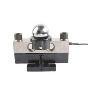
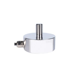
The Series CNR950 load cells are compact canister designs for
compression force applications. These load cells incorporate an
integral spherical load button.
The CNR950 is constructed of welded stainless steel for the
most demanding application environments. Hermetic bolt on
or welded on stainless steel electrical connectors are standard
for most sizes. Additional features include shock and vibration
protection and each unit is shipped with a 5 point calibration
record traceable to NIST, both as standard.
Standard Features
• Ranges from 2000-2,000,000 lbs.
• In-Line Loading
• Compact Size
• 0.25% Accuracy
• Welded, Stainless Steel Construction
• -65°F to 250°F Operation
• mV/V Output
Optional Features
• Amplified Outputs
• Threaded Mounting Features
• Special Calibrations
• Multiple Bridges
• -320°F to 400°F temperature ranges (mV/V unit)
• Integral high level output (analog or digital) 50K or greater
Performance
Ranges
2K – 2000K lb, see chart on page 2.
OUTPUT
2 mV/V nominal.
Accuracy
0.25% FSO BFSL.
Linearity
0.15% FSO typical.
Hysteresis
0.15% FSO typical.
Repeatability
0.05% FSO.
Compensated Temperature Range
70°F to 170°F.
Operating Temperature Range
-65°F to 250°F.
Temperature Effect on Zero
±0.005% FSO/ºF.
Temperature Effect on SPAN
± 0.005% Reading/ºF.
Zero Balance
1% FSO.
Bridge Resistance
350 or 700 Ohms nominal.
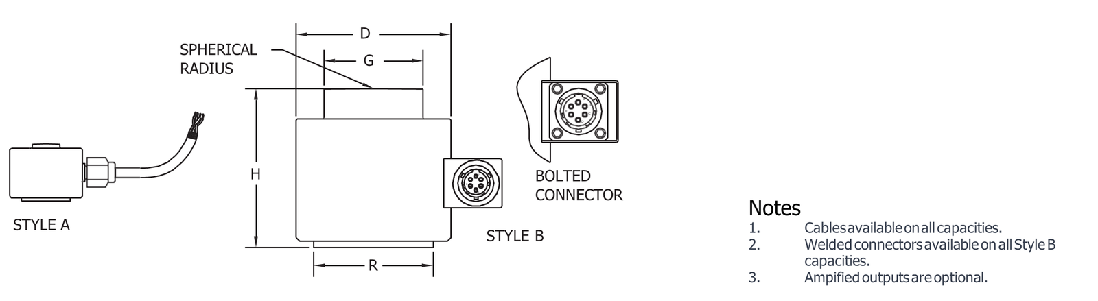
| CAPACITY (LBS) | HEIGHT H | DIAMETER OVERALL D | DIAMETER BUTTON G | DIAMETER BASE R | STYLE | CONNECTOR STYLE |
| 2K, 5K | 0.75 | 0.88 | 0.28 | 0.38 | A | CABLE |
| 10K | 1.00 | 1.19 | 0.56 | 0.70 | A | CABLE |
| 25K | 1.37 | 1.75 | 0.85 | 1.07 | A | CABLE |
| 50K | 1.80 | 2.19 | 1.18 | 1.38 | B | WELDED |
| 100K | 2.50 | 2.75 | 1.66 | 1.75 | B | WELDED |
| 250K | 3.88 | 3.85 | 2.62 | 2.80 | B | WELDED |
| 500K | 5.75 | 4.44 | 3.60 | 3.81 | B | WELDED |
| 1000K | 7.50 | 6.45 | 5.06 | 5.35 | B | BOLTED |
| 2000K 11.50 9.50 | 7.00 | 7.00 | B | BOLTED | ||
Mechanical Characteristics
Calibration
Standard calibration is 5 pts (0, 50%,
100%, 50%, 0 of Range) compression.
Maximum Overload Without Damage
150% Range.
CONSTRUCTION
Welded stainless steel.
Electrical Characteristics
ANALOG OUTPUTS
Excitation
10 Vdc or 10 Vac.
Insulation Resistance
Greater than 5000 MOhms at 50 Vdc.
Electrical Termination
See table above.
Cables
Cables for 2K, 5K are 4 conductor, 30 AWG shielded, color coded.
Cables for 10K, 25K are 4 conductor, 24 AWG shielded, color coded.
Electrical Characteristics
wiring
Units with connector Units with cable Connector Pins Cable Wire
| A | +EXC | RED +EXC |
| B | +SIG | GREEN +SIG |
| C | -SIG | WHITE -SIG |
| D | -EXC | BLACK -EXC |
| E, F | N/C |
Customer specified wiring codes are available