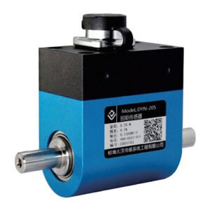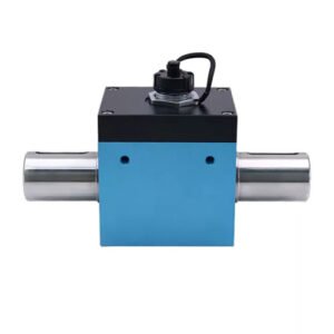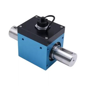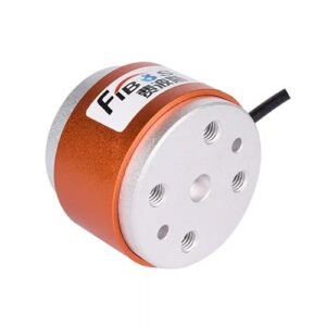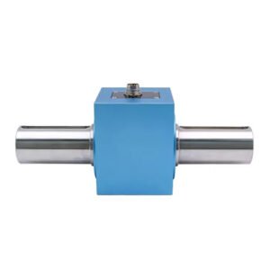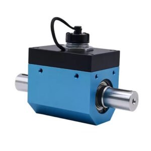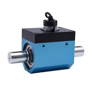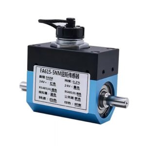


KWR61N66 61mm 66Nm Static Torque Sensor RS485 for Robot Joint

Description

In the design process of KWR61N66 torque sensor with RS485 digital output, circuit design is the core link to ensure that the sensor can accurately and stably convert torque into measurable electrical signals. Its design quality directly affects the performance, accuracy, response speed, and reliability of the sensor.
Sensor circuits typically consist of several key modules, including signal conditioning circuits, analog-to-digital conversion circuits (ADCs), microprocessors and control circuits, power management circuits, communication interface circuits, and protection and isolation circuits. These modules work together to achieve signal acquisition, processing, and output. Module 1: The signal conditioning circuit amplifies, filters, and linearizes the weak signal output by the sensor to match the input requirements of subsequent circuits. Usually composed of amplifiers and filters, such as operational amplifiers (Op Amps) and instrumentation amplifiers (Instrumentation Amplifiers), used to amplify weak signals, and low-pass, high pass, and band-pass filters used to suppress noise and interference. Module 2: The function of analog digital conversion circuit (ADC) is to convert analog signals into digital signals for processing by microprocessor or digital system. Key parameters include resolution (digits), sampling rate, conversion time, quantization error, etc. Module 3, the functions of the microprocessor and control circuit include further processing of digital signals (such as filtering, calibration, compensation) to achieve the intelligence of sensors. Usually composed of microcontrollers (MCUs) and digital signal processors (DSPs), microcontrollers are typically used to execute algorithms, control peripheral circuits, and implement communication protocols. Digital signal processors are used for complex signal processing tasks. Module 4, the main function of the power management circuit is to provide stable power supply for sensors and their circuits, and reduce power consumption. It is usually composed of a voltage regulator and a power switch. Voltage regulators include LDO (Low Dropout Linear Regulator) and DC-DC converters. The power switch is used to control the power supply status of the circuit and achieve low-power mode. Module 5, communication interface circuit, can achieve data transmission between sensors and external devices (such as upper computer, other sensors). Common interfaces are divided into wired interfaces and wireless interfaces. SPI, I ² C, UART, RS-485, etc. are wired interfaces, while Bluetooth, Wi Fi, ZigBee, LoRa, etc. are wireless interfaces. Module 6, protection and isolation circuit, can protect sensors and their circuits from damage such as overvoltage, overcurrent, electrostatic discharge (ESD), etc. Composed of transient voltage suppressor (TVS) and optocoupler isolator, it is used to suppress overvoltage pulses, achieve electrical isolation, and improve safety.

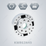
Model of KWR61N66