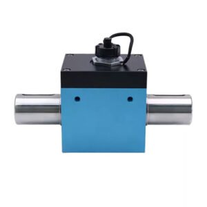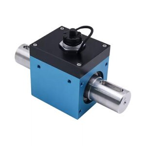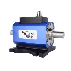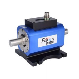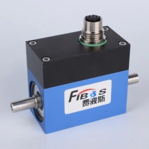


KWR61N150 Static 61mm 150Nm RS485 Torque Sensor for Robot Joint

Description

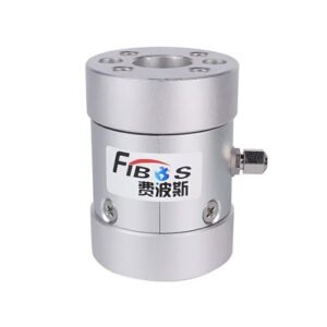
In the design process of KWR61N150 torque sensor, the fitting installation dimensions were considered. In the common method of measuring torque using strain gauges attached to the bottom of the flexible wheel of the joint harmonic reducer, since the joint housing and harmonic reducer have been determined, the maximum outer diameter of the sensor (61mm) should be set to be smaller than the inner diameter of the joint upper housing; The centerline diameter of the bolt circle on the inner rim of the sensor is consistent with the bolt hole position on the flexible wheel flange; The size of the strain beam can be optimized based on the minimum weight of the strain beam, with the width, thickness, and length of the strain beam as variables for optimal design. This product is made of hard aluminum alloy 7075-T6 material, which is an excellent elastic material with high strength, low cost, good cutting performance, and low density. In addition, precipitation hardened stainless steel and crystalline alloy 17-4PH can also be selected for sensor design. The structure and size of the torque sensor can be determined based on the alloy properties and torque sensor technology requirements, combined with finite element analysis.

The elastic body of KWR61N150 torque sensor adopts a spoke type structure, consisting of inner and outer wheel hubs and a middle strain beam. Four strain gauges are attached to the strain beam and connected to the full bridge circuit to measure torque. When there is a harmonic reducer as the output stage in the transmission chain, due to the large strain generated by the flexible wheel of the harmonic reducer during operation, the flexible wheel can replace the elastic body without changing the joint structure or adding additional flexibility, so this structure has certain advantages. However, there is a large ripple in measuring strain on the flexible wheel. Distinguishing between the target signal and the ripple and eliminating the ripple is the key to improving the accuracy of the torque sensor. There are two main sources of strain on the flexible wheel, one is external torque, which is the target signal to be measured; The other is the rotation of the wave generator, which is the interference signal (ripple signal) that needs to be eliminated. The elimination methods usually include bridge compensation method (strain gauges located 90 ° and 45 ° apart generate ripple signals with a phase difference of 180 °, which are superimposed to achieve ripple cancellation), weighted superposition method (independent half bridge circuit channel signal weighted superposition cancellation uniformly distributed around the circumference), and filtering cancellation (Kalman filtering method for filtering torque signals).
Model of KWR61N150

Joint torque sensors play an important role in the aerospace field, and KWR61N150 can be used to monitor the torque output of mechanical components of aircraft, satellites, and other spacecraft, ensuring the normal operation and safety of the aircraft. For example, installing torque sensors on the landing gear, control surfaces, and other parts of an aircraft can monitor the torque status of these components in real time, detect and address potential safety hazards in a timely manner. According to literature, torque sensors play a crucial role in aircraft control systems, which can improve the stability and safety of the aircraft. In addition, in automated production lines, the KWR61N150 joint torque sensor can be used to monitor the torque output of various mechanical components within a range of 150Nm, ensuring the normal operation of the production line and product quality. For example, on the assembly line, real-time monitoring of joint torque can ensure the accuracy and consistency of the assembly process, improve production efficiency and product quality. Research has shown that the application of torque sensors in automated production lines can improve production efficiency and product quality, while reducing production costs. For example, in the process of automobile manufacturing, torque sensors can be used to monitor the torque output of key components such as engines and transmissions, ensuring that the performance of these components meets design requirements.