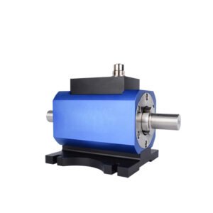


BRG62050A Contactless Torque Sensor
The compact contactless torque sensor, built on advanced strain gauge technology, is designed for high-speed, small-scale torque measurement. It outputs a 5-15kHz frequency signal or a 4-20mA current signal, ideal for long-distance transmission. With its small size, easy installation, and strong anti-interference capability, it’s an excellent alternative to imported torque sensors.
Our advantage of Contactless Torque Sensor
Non-Contact Measurement
As the name implies, these sensors measure torque without any physical contact between the sensor and the rotating shaft. This eliminates wear, friction, and the need for shaft modifications like tapped holes or flats
Wide Torque Range
Contactless torque sensors are available with full-scale torque ranges from as low as 0.02 Nm to as high as 20,000 Nm, making them suitable for a broad range of applications from small servomotors to large industrial machinery
Bidirectional Measurement
They can measure torque in both clockwise and counterclockwise directions, enabling measurement of dynamic torque reversals
Contactless torque sensors typically provide analog output signals, such as ±5V or ±10V, proportional to the measured torque. This allows for easy integration with existing control systems and data acquisition equipment
Static and Dynamic Measurement
While primarily designed for dynamic torque measurement on rotating shafts, some contactless torque sensors can also measure static torque when the shaft is stationary.
The non-contact operating principle allows for a compact and lightweight sensor design, facilitating easy installation and minimizing the impact on system dynamics.
High Durability
With no physical contact or wear components, contactless torque sensors offer high durability and long service life, even in harsh industrial environments
Some contactless torque sensors provide optional high-level output signals, such as digital or fieldbus interfaces, for seamless integration with modern control systems.
Industry Solutions
the application of the Contactless Torque Sensor
Automotive Applications
1.Electric power steering systems: Measure input torque for torque overlay and assist control.
2.Electric and hybrid vehicle drivetrains: Monitor torque in motors, gearboxes, and driveshafts for control and diagnostics.
3. Dynamometers and test benches: Measure torque output of engines, transmissions, and other rotating components during testing.
01
Industrial Machinery
1. Machine tools: Monitor cutting tool torque for process optimization and tool wear detection.
2. Robotics: Provide torque feedback in robotic joints and manipulators for precise force control.
3. Packaging and converting machines: Measure web tension and torque in winding, slitting, and coating processes
02
Motion Control
1. Servo motors and actuators: Enable precise torque control in high-performance motion control systems.
2. Conveyor systems: Monitor torque in conveyor drives for overload protection and process monitoring
03
Test and Measurement
1.Bicycles and e-bikes: Measure pedal torque for electric assist control and power management.
2. Industrial pumps and compressors: Monitor torque in rotating equipment for condition monitoring and predictive maintenance.
3. Wind turbines: Measure torque in drivetrain components for load monitoring and control
04
Technical Parameters
| Index name | Technical index |
| Range | 3, 5, 10, 20, 30, 50, 100Nm (Optional) |
| Power supply | ±15V DC (Applicable frequency signal output), 24V DC (Applicable voltage or current signal output) |
| Torque signal | 5~15Khz (Amplitude 12V,zero point 10kHz), 4~20mA, 1~5V, 0-10V (Optional) |
| range of rotation | 0~1000, 3000, 6000, 8000 speed/min |
| Speed signal | The standard product does not have the measuring speed, if the length of the measuring speed is increased 30mm |
| Precision | ±0.25%, ±0.5% |
| Yearly stability | 0.25%/year |
| Insulation resistance | ≥2000MΩ(100VDC) |
| working temperature | -20~60℃ (can be -20~120℃) |
| Relative humidity | 0~90%RH |
| Overload capacity | 150% |
| Frequency response | 1ms |
Dimension (mm)


")
")
Tips for use
1. In cases of bending moments, the torque sensor and equipment base should be flexibly mounted to allow for movement.
2. If vibration occurs, the power supply and load equipment must be securely fastened.
3. Ensure proper electrical connections are made according to the specifications.
4. If any issues arise during use, please contact us promptly for assistance.
Installation Steps
1. Mounting Location: Choose a location that minimizes vibration and allows for proper alignment with the driveline. Install the sensor as close to a bearing as possible to reduce the risk of critical speed issues.
2. Use Proper Couplings: Install couplings at both ends of the torque sensor. Depending on the application, you can choose between floating or fixed installations. Floating installations may require half couplings, while fixed installations should use full couplings for better stability and measurement accuracy.
3. Align the Sensor: Proper alignment is crucial. Use alignment tools to ensure that the sensor and the connected shafts are aligned correctly. Misalignment can lead to inaccurate readings and sensor damage.
4. Balancing: Check if the torque sensor is balanced at the factory. Balance the entire driveline after installation to prevent vibrations that could affect measurement accuracy.
5. Secure Bolts: Use the recommended bolts as specified in the manual and tighten them according to the torque sensor’s capacity. This ensures that the sensor is securely mounted and can handle operational stresses.
6. Check Air Gap: Maintain the proper air gap between the rotor and stator, typically around 2 mm on each side, to ensure optimal performance.
7. Testing: After installation, conduct a test run at low speeds to check for consistent torque readings. Any significant fluctuations may indicate misalignment or installation issues that need to be addressed