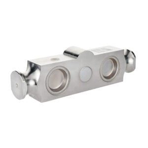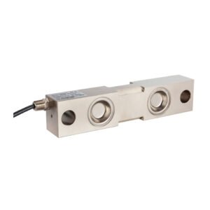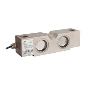


Single-Ended Shear Beam Load Cell | OSBKT
The Accurate, Low Cost and Robust Weight Measurement Option Applied Measurements OSBKT single-ended shear beam load cell is suitable for medium capacity weighing applications such as hoppers and vessels where a highly accurate measurement system is required. They are also suitable for conveyor weighing applications. The OSBKT single-ended shear beam load cell’s high integrity IP67 body and alloy steel construction make it ideal for general purpose industrial weighing applications where low-cost is a primary consideration. Two mounting assemblies are available to suit the OSBKT single ended shear beam load cell; the Vessel Mount for static applications and the Shock / Anti-Vibration Mount for mixer, feed hopper and conveyor applications where vibration or transient loads may occur. For mount dimensions, please download the datasheet. For hazardous environments, our OSBKT single-ended shear beam load is available with ATEX (EEx ia IIC T6) hazardous area approvals. Other discontinued third party products like the AW420/01000 can be easily substituted by our OSBKT-1000kg-003-000 product and will deliver similar performance and longevity.
Technical Specifications
| OSBKT | OSBST | UNITS | |
|---|---|---|---|
| Rated Capacity (RC) | 0-250, 0-500, 0-1000, 0-2000 | 0-500, 0-1000, 0-2000, 0-5000 | kgf |
| Operating Modes | Compression Only | ||
| Sensitivity (RO) | 2.0 ±0.1% | mV/V | |
| Zero Balance/Offset | <2.0 | ±%/Rated Output | |
| Zero Return after 30 mins. | <0.025 | ±%/Rated Capacity | |
| Accuracy | <0.020 | ±%/Rated Capacity | |
| Temperature Effect on Zero | <0.0023 | ±%/Rated Output/ ˚C | |
| Temperature Effect on Sensitivity | <0.0010 | ±%/Applied Load/ ˚C | |
| Input Resistance | 380 nominal | Ohms | |
| Output Resistance | 350 nominal | Ohms | |
| Insulation Resistance | >2000@50Vdc | Megohms | |
| Excitation Voltage | 10 recommended (2-15 acceptable) | Volts AC or DC | |
| Operating Temperature Range | -20 to +70 | ˚C | |
| Compensated Temperature Range | -10 to +40 | ˚C | |
| Storage Temperature Range | -20 to +70 | ˚C | |
| Safe Overload | 150 | % of Rated Capacity | |
| Ultimate Overload | 300 | % of Rated Capacity | |
| Deflection @ Rated Load | <0.4 | mm | |
| IP Rating (Environmental Protection) | IP67 | IP68 | |
| Weight (excluding cable) | 0.9 (250kg, 500kg & 1000kg), 1.1 (2000kg), 2.1 (5000kg) | 0.9 (500kg, 1000kg & 2000kg), 1.9 (5000kg) | kg |
| Fatigue Life | 108 cycles typical (109 cycles on fatigue-rated version) | ||
| Cable Length (as standard) | 3 | 5 | metres |
| Cable Type | 6 core screened, PUR sheath, Ø6mm | ||
| Construction | Nickel Plated Alloy Steel | Stainless Steel | |
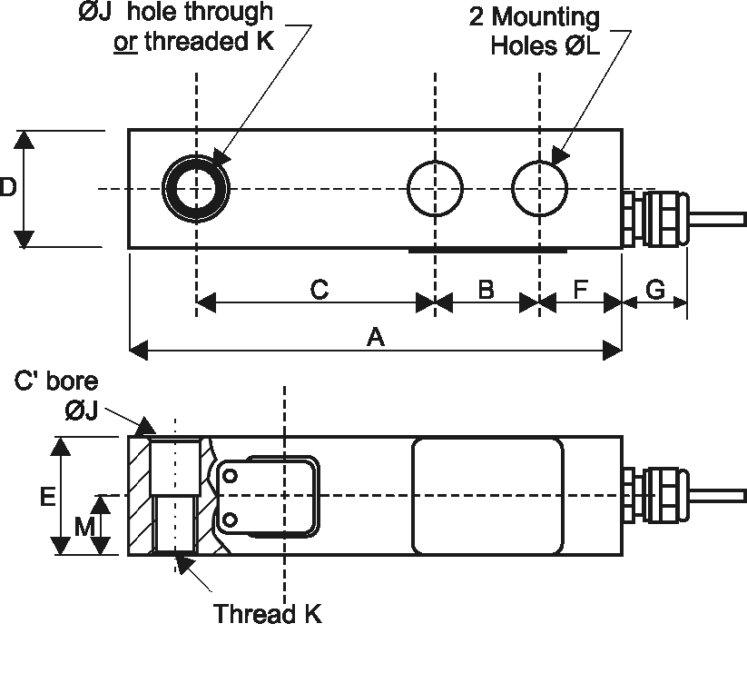
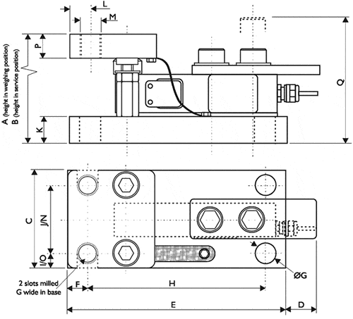
Product Dimensions
|
Model
|
Capacity (kg)
|
A
|
B
|
C
|
D
|
E
|
F
|
G
|
ØJ
|
K
|
ØL
|
M
|
|---|---|---|---|---|---|---|---|---|---|---|---|---|
|
OSBKT
|
250, 500, 1000
|
130
|
25.4
|
76.2
|
30.5
|
30.5
|
16
|
19
|
13.5
|
M12 x 1.75
|
13.5
|
16
|
|
OSBKT
|
2000
|
130
|
25.4
|
76.2
|
30.5
|
36
|
16
|
19
|
13.5
|
M12 x 1.75
|
13.5
|
16
|
All dimensions are in mm
Wiring Details
| Wire | Designation |
|---|---|
| Red | +ve excitation |
| Black | -ve excitation |
| Green | +ve signal |
| White | -ve signal |
| Blue | +ve sense |
| Brown | -ve sense |
| Yellow | Cable Screen – to ground – not connected to load cell body |
Ordering Codes & Options
| Core Product | Capacity (inc Engineering Units) | Cable Length (m) | Specials Code | Example Result |
|---|---|---|---|---|
| OSBKT | 250kg | 003 | 000 | OSBKT-250kg-003-000 |
| OSBKT | 500kg | 003 | 000 | OSBKT-500kg-003-000 |
| OSBKT | 1000kg | 003 | 000 | OSBKT-1000kg-003-000 |
| OSBKT | 2000kg | 003 | 000 | OSBKT-2000kg-003-000 |
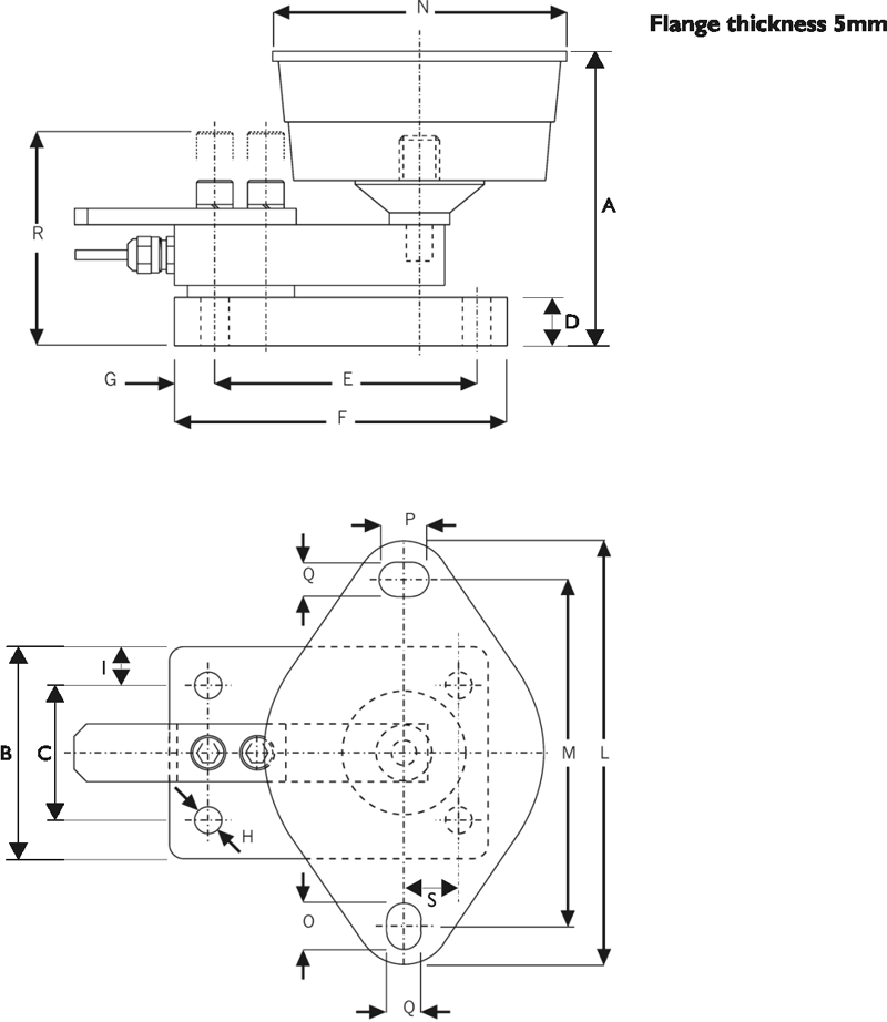
Mounting Accessories
VESSEL MOUNT ASSEMBLY
- Simple to Install Into New or Existing Installations.
- Can be Installed With or Without the Load Cells in Position
- Stainless Steel Construction
- Easy Lifting and Removal of Load Cell
- Rugged Construction
- Reduces Installation Time
- Permanent Integral Safety Vessel Jacking System for your Vessel
- Anti-Lift Mechanism for Greater Vessel Stability
- Maximum Safety Protection from the Effects of Wind or Accidental Collision are Built-In.
- Heavy Duty Earth Straps Ensure that no Potential Difference Between the Upper and Lower Plates Occurs.
- Low Resistance Path Assists in Removing Strong Welding Currents.
- Substantial Protection Plate is Positioned Above the Cable Outlet to Prevent Damage by Falling Objects or Misuse.
| MODEL | OSBKT & OSBST 500-2000kg | OSBKT & OSBST 5000kg |
|---|---|---|
| A | 100 | 135 |
| B | 108 | 143 |
| C | 110 | 153 |
| D | 51 | 47 |
| E | 165 | 216 |
| F | 15 | 20 |
| G | 14 | 19.8 |
| H | 130 | 162 |
| I | 20 | 31.5 |
| J | 70 | 90 |
| K | 24 | 29 |
| L | 15 | 20 |
| M | M16 | M16 |
| N | 70 | 90 |
| O | 20 | 31.5 |
| P | 24 | 29 |
| Q | 111 | 159 |
SHOCK MOUNT ASSEMBLY
- Enables Weighing when a Vessel or Hopper is Subjected to External Forces
- Plated Steel Construction
- Minimises the Effects of Vibration
- Ease of Assembly Reduces Installation Time
- Complete Assembly is Supplied
| MODEL | OSBKT & OSBST 500-2000kg |
|---|---|
| A | 146 |
| B | 110 |
| C | 70 |
| D | 24 |
| E | 130 |
| F | 165 |
| G | 20 |
| H | 14 |
| I | 20 |
| L | 220 |
| M | 180 |
| N | 146 |
| O | 24 |
| P | 26 |
| Q | 18 |
| R | 106 |
| S | 30 |