

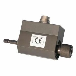
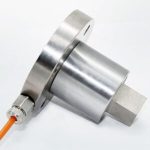
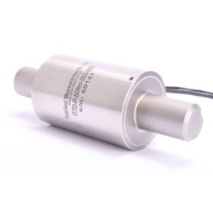
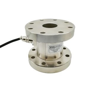
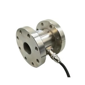
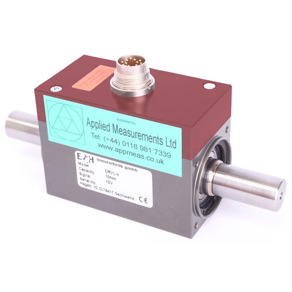
Shaft type Brushless Rotary Torque Sensor | DRVL
Accurate and Maintenance-Free, with Built-In Signal Conditioning The DRVL non-contact torque sensor series manufactured by ETH Messtechnik in Germany builds on the existing DRFL series with some significant improvements. Its integral signal conditioner now outputs 2 standard signals of (10V and 10kHz ± 5kHz) with a bandwidth of 200Hz as standard, while a conditioner with a 1kHz bandwidth is optional. The output level for speed and angle signals can now be adjusted from 5V up to 24V making it compatible with PLC acquisition units and many more evaluation devices. Accuracy is guaranteed to <±0.1% of the rated capacity and there are also higher accuracy versions available to <±0.05%. They feature extended surge tests to ensure better electromagnetic compatibility protecting the sensor from unwanted electromagnetic interference and damage. The DRVL series non-contact torque sensors are directly compatible with the established DRFL making installation fast and simple. They can also be supplied with optional base and customised couplings to ensure that you achieve the best possible torque measurement whilst making the task of installation as straightforward as possible.
Technical Specifications
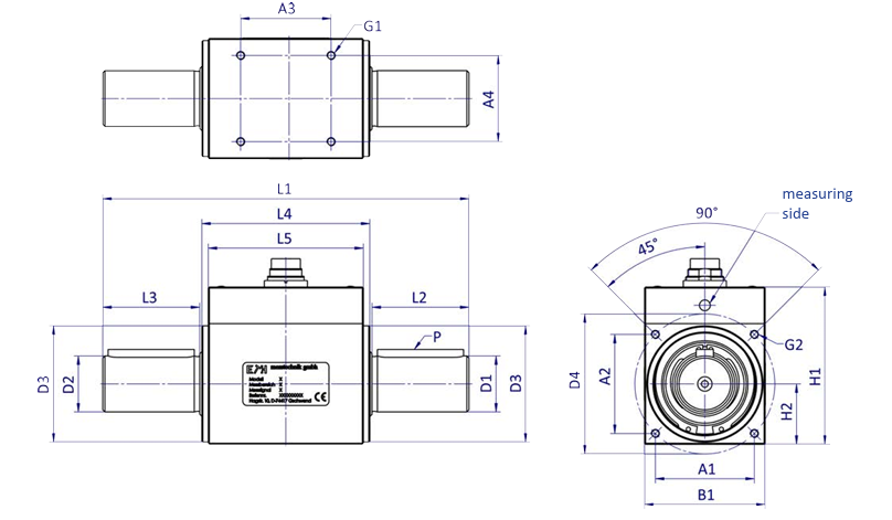
Product Dimensions
| Model | DRVL | DRVL-I | DRVL-Ib | DRVL-II | DRVL-III | DRVL-IV | DRVL-V | DRVL-VI | |
|---|---|---|---|---|---|---|---|---|---|
| Torque | 0,02 | 0,05 | 2 | 1 | 5 | 50 | 500 | 2000 | 10 |
| Ranges | 0,05 | 0,1 | 2 | 10 | 100 | 1000 | 3000 | 15 | |
| (± 0 – … Nm) | 0,1 | 0,2 | 5 | 20 | 150 | 1300 | 4000 | 20 | |
| 0,5 | 10 | 30 | 200 | 1500 | 5000 | ||||
| 1 | 50 | 300 | |||||||
| Dimensions: | (other ranges upon request; General tolerances DIN 2768-m) | ||||||||
| L (mm) | 82 | 89 | 95 | 110 | 145 | 170 | 270 | 320 | 355 |
| B1 (mm) | 32 | 28 | 36 | 42 | 56 | 88 | 105 | 168 | |
| H (mm) | 47 | 54 | 58 | 58 | 73 | 104 | 121 | 185 | |
| H1 (mm) | 14 | 14 | 18 | 21 | 28 | 44 | 52,5 | 84 | |
| H2 (mm) | 22 | (→ LK) | (→ LK) | (→ LK) | (→ LK) | (→ LK) | (→ LK) | — | |
| Ø D1 g6 (mm) | 3 | 8 | 8 | 10 | 15 | 26 | 45 | 70 | 110 |
| Ø D2 g6 (mm) | 3 | 5 | 6 | 10 | 15 | 26 | 45 | 70 | 110 |
| Ø D3-0,1 (mm) | 15 | 27 | 32 | 38 | 54 | 80 | — | — | |
| Ø LK ± 0,1 (mmm) | (→ B1/H2) | 32 | 38 | 46 | 65 | 98 | — | — | |
| L1 | 63 | 62 | 68 | 79 | 72 | 84 | 95 | 121 | |
| L2 | 7,5 | 11 | 14 | 18 | 30 | 45 | 85 | 110 | 115 |
| L3 | 7,5 | 10 | 14 | 18 | 30 | 45 | 85 | 110 | 115 |
| L4 | 67 | 66 | 72 | 83 | 78 | 90 | — | — | |
| A1 | 50 | 40 | 56 | 60 | 42 | 46 | 75 | 91 | |
| A2 | 24 | 22 | 24 | 32 | 40 | 70 | 85 | 138 | |
| G1 | M2,5 x 5 deep | M3 x 5 deep | M3 x 6 deep | M3 x 6 deep | M4 x 8 deep | M6 x 12 deep | M8 x 16 deep | M10 x 16 deep | |
| G2 | M2,5 x 5 deep | M3 x 6 deep | M3 x 6 deep | M3 x 6 deep | M4 x 8 deep | M6 x 12 deep | — | — | |
| P (DIN 6885) optional* | — | — | 2xA3x3x14 | 2x A5x5x25 | 2x A8x7x40 | 4xA14x9x80 | 4x A20x12x100 | — | |
| Weight (g) | 200 | 170 | 340 | 600 | 1300 | 4500 | 11500 | 33000 | |
| Max RPM | 20000 | 37000 | 26000 | 19000 | 13500 | 7900 | 6300 | 4000 | |
| *Note: When supplied with this option, DRVL-IV & DRVL-V have 2x keyways at each end of the shaft positioned 180º apart. | |||||||||
Wiring Details – AK12.4 Cable Assembly
| Pin | Colour | Designation for DRVL Torque Transducer |
|---|---|---|
| A | Green | Torque Output Signal: Frequency 10kHz ±5kHz |
| B | Red / Blue | Angle Output: Track B = 90° |
| C | Yellow | Torque Output Signal: ±10Vdc |
| D | White | Torque Output GND/0V (note: can be connected to supply GND / Pin E) |
| E | Grey | Supply GND/0V & Angle/Speed Output GND/0V |
| F | Pink | Supply: +9Vdc to +28Vdc |
| G | Grey / Pink | Speed/Angle Output: Track A = 0° |
| H | Purple | Memory Chip (factory use only) |
| J | Black | Sensor Health Check Signal (factory use only) |
| K | Red | Control Input (factory use only) |
| L | Brown | Torque Output Signal: Frequency 10kHz ±5kHz (inverted) |
| M | Blue | External Voltage Reference Input for Speed/Angle Signal (optional) |
| Screen | Connect cable screen to earth |


