


Miniature In-Line Load Cell | Tension and Compression | DDE
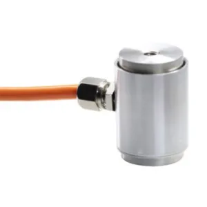
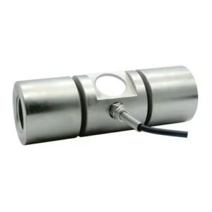
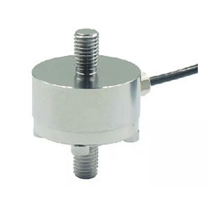
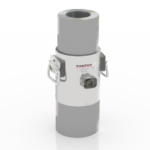
Compact, Low Deflection and Comes with Integral Mounting Threads Applied Measurements DDE miniature in-line load cell is suitable for use in both tension and compression and offers a very low profile body coupled with integral mounting threads to allow use in applications with restricted mounting space where other in-line load cell designs such as S-Beam load cells are too large. The DDE’s small size means that weight is kept to a minimum, this, in conjunction with its low deflection, results in a high stiffness assembly and makes the load cell suited to the measurement of fast changes in load and high-frequency transients. The DDE miniature in-line load cell is currently being used in many applications including automotive production, cable tension monitoring and suspension force monitoring. Customised versions with different thread sizes, specific dimensions and interim capacity can also be provided if required. For a submersible in-line load cell please see Applied Measurements DDEN fully submersible load cell which has a protection rating of IP68 suitable for long-term immersion.
Technical Specifications
| Rated Capacity (RC) | N | 0-100, 0-250, 0-500, 0-1000, 0-2500, 0-5000, 0-10000, 0-20000, 0-50000 |
|---|---|---|
| Operating Modes | Tension/Compression / Tension & Compression | |
| Sensitivity (RO) | mV/V | 2.0 nominal (1.2 approx on 100N) |
| Zero Balance/Offset | ±%/Rated Output | <1.0 |
| Output Symmetry (tension vs. compression | ±%/Rated Output | <1 |
| Non-Linearity | ±%/Rated Output (BFSL) | <0.3 |
| Hysteresis | ±%/Rated Output | <0.3 |
| Repeatability | ±%/Rated Output | <0.2 |
| Temperature Effect on Zero | ±%/Rated Output/ ˚C | <0.005 |
| Temperature Effect on Sensitivity | ±%/Applied Load/ ˚C | <0.005 |
| Input Resistance | Ohms | 750 nominal |
| Output Resistance | Ohms | 700 nominal |
| Insulation Resistance | Megohms | >5000 @ 50Vdc |
| Excitation Voltage | Volts AC or DC | 10 recommended (2-15 acceptable) |
| Operating Temperature Range | ˚C | -20 to +80 |
| Compensated Temperature Range | ˚C | 0 to +70 |
| Storage Temperature Range | ˚C | -20 to +80 |
| Safe Overload | % of Rated Capacity | 150 |
| Ultimate Overload | % of Rated Capacity | 200 |
| Maximum Allowable Sideload | % of Rated Capacity | <5 |
| Deflection @ Rated Capacity | mm | See dimensions table |
| Fundamental Resonant Frequency* | kHz | See dimensions table |
| IP Rating (Environmental Protection) | IP65 | |
| Weight (excluding cable) | grams | 150 nominal |
| Fatigue Life | 108 cycles typical (109 cycles on fatigue-rated version) | |
| Cable Length (as standard) | metres | 2 |
| Cable Type | 4-core + screen, PVC sheath, Ø3.5 typical | |
| Construction | Stainless Steel | |
| Resolution: | 1 part in 250,000 (with appropriate instrumentation) | |
| *The resonant frequency is calculated with the body of the load cell attached to a large plate, ensuring that only the sensing element oscillates: This is vital to achieve the highest natural frequency and subsequent frequency response. | ||
Product Dimensions (mm)

|
CAPACITY (N)
|
A
|
B
|
C
|
D
|
Deflection mm | Resonant Frequency kHz |
|---|---|---|---|---|---|---|
| 100 | 50 | 15 | 20 | M12 | 0.10 | 0.53 |
| 250 | 50 | 15 | 20 | M12 | 0.10 | 0.84 |
| 500 | 50 | 15 | 20 | M12 | 0.07 | 1.42 |
| 1000 | 50 | 15 | 20 | M12 | 0.05 | 2.37 |
| 2500 | 50 | 15 | 20 | M12 | 0.03 | 4.84 |
| 5000 | 50 | 15 | 20 | M12 | 0.02 | 8.39 |
| 10000 | 50 | 12.5 | 25 | M12 | 0.04 | 13 |
| 20000 | 50 | 12.5 | 25 | M12 | 0.04 | 18 |
| 50000 | 56 | 18 | 20 | M16 | 0.03 | 25 |
Wiring Details
| Wire | Designation |
|---|---|
| Red | +ve excitation |
| Blue | -ve excitation |
| Green | +ve signal (compression) |
| Yellow | -ve signal |
| Screen | To ground – not connected to load cell body |
Ordering Codes & Options
| Core Product | Capacity (inc Engineering Units) | Cable Length (m) | Specials Code | Example Result |
|---|---|---|---|---|
| DDE | 100N | 002 | 000 | DDE-100N-002-000 |
| DDE | 250N | 002 | 000 | DDE-250N-002-000 |
| DDE | 500N | 002 | 000 | DDE-500N-002-000 |
| DDE | 1000N | 002 | 000 | DDE-1000N-002-000 |
| DDE | 2500N | 002 | 000 | DDE-2500N-002-000 |
| DDE | 5000N | 002 | 000 | DDE-5000N-002-000 |
| DDE | 10,000N | 002 | 000 | DDE-10kN-002-000 |
| DDE | 20,000N | 002 | 000 | DDE-20kN-002-000 |
| DDE | 50,000N | 002 | 000 | DDE-50kN-002-000 |
Mounting And Installation Accessories
Rod End Bearings for Tension Use
Designed to align forces through the principle axis of the load cell thus reducing the effects of extraneous forces, hence offering improved performance from the cell. Rod End Bearings are used where tensile forces are being applied. Maintenance-free rod ends are a complete units made up of a housing with both an integral shank (with an internal or external thread) and a maintenance-free spherical plain bearing, located within the housing. Key Features:
- Supports radial loads in a tensile or compressive direction.
- Suitable for unilateral loads – can support alternating loads and alternating loads in combination with bearing GE..UK-2RS, please consult sales.
- Zinc plated for corrosion resistance.
- Are maintenance-free.
- Fitted with radial spherical plain bearings GE..UK
- Hard chromium/PTFE composite sliding contact surfaces.
- Enables compact adjacent construction thanks to its thin-walled design of the eye housing.
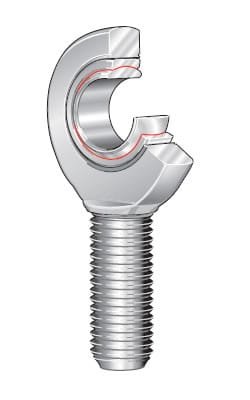
GIR..UK (right hand thread) To ISO 12 240-4, dimension series E, type F Shank with internal thread Maintenance-free ISO 12 240-4, dimension series E, type F Sliding contact surface: hard chromium/PTFE Series GIR..UK Sliding material: PTFE composite
| LOAD CELL | SHAFT DIAMETER | ORDERING CODE | MASS | DIMENSIONS | |||||||||
|---|---|---|---|---|---|---|---|---|---|---|---|---|---|
| d | WITHOUT SEALS | WITH SEALS | ≈ kg | d | D | B | dK | d1 | d2 | d3 | d4 | h1 | |
| DDE-100N to 20kN | 12 | GIR 12 UK | – | 0.096 | 12-0.008 | 22 | 10-0.12 | 18 | 14.9 | 34 | M12 | 17.5 | 50 |
| DDE-50kN | 17 | GIR 17 UK | – | 0.22 | 17 -0.008 | 30 | 14-0.12 | 25 | 20.7 | 46 | M16 | 24 | 67 |
| LOAD CELL | Degrees | Chamfer Dimension | Basic Load Ratings | Radial Internal Clearance | Shaft Diameter | ||||||||
|---|---|---|---|---|---|---|---|---|---|---|---|---|---|
| C1 | α | l3 | l4 | l5 | l7 | d5 | W | r1s min. | dyn. Cr N | stat. C0r N | d | ||
| DDE-100N to 20kN | 8 | 11 | 23 | 67 | 6.5 | 18 | 22 | 19 | 0.3 | 11 400 | 30 400 | 0 – 0.032 | 12 |
| DDE-50kN | 11 | 10 | 34 | 90 | 10 | 23 | 30 | 27 | 0.3 | 22 400 | 56 500 | 0 – 0.04 | 17 |