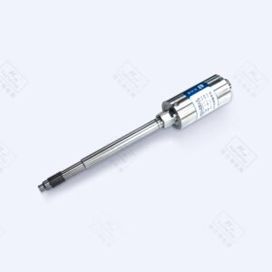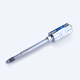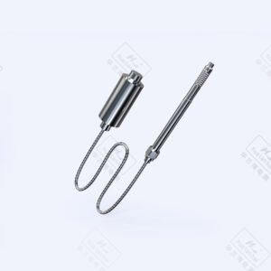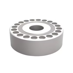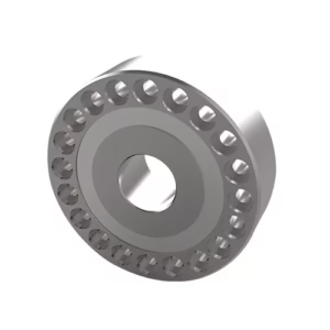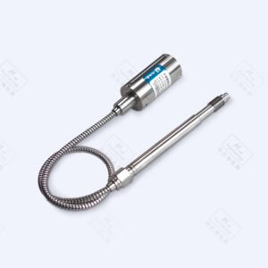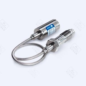

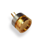


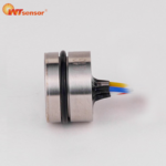
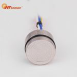
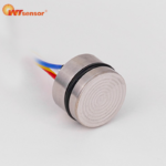
Piezoresistive Silicon Pressure Sensor Φ19mm PC10P
Features
■With constant current and constant voltage excitation options
■ Imported highly reliable pressure die
■ Wide temperature compensation
■ Normalized output available
■ Compensation board filled with glue for protection against moisture
■ Φ19mm standard OEM
■ All 316L material
■ High performance, all solid, high reliability
■ 18 months warranty period
Applications
■ Process control systems
■ Pressure calibration instruments
■ Refrigeration equipment and HVAC control
■ Hydraulic systems and valves
■ Level measurement
■ Biomedical instruments
■ Ships and navigation
■ Aircraft and avionics systems
■ Weaponry
Product Parameters
| Electrical performance parameters | |||
| Pressure range | -100kPa~0~10kPa…60MPa | ||
| Pressure reference | Gauge pressure, Absolute pressure, Sealed gauge pressure | ||
| Excitation | 1.5mA recommended for constant current
10V recommended for constant voltage |
||
| Input impedance | Constant current: 2kΩ~5kΩ
Constant voltage: 3kΩ~18kΩ |
||
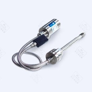
| Electrical connection | Gold-plated KOVAR pin or silicon soft wire | ||
| Compensation temp. | Constant current: 0℃~60℃(≤70kPa),
-10℃~70℃(other ranges) |
||
| Operating temp. | -40℃~125℃ | ||
| Storage temp. | -40℃~125℃ | ||
| Insulation resistance | ≥200MΩ/250VDC | ||
| Response time | ≤1ms (up to 90%FS) | ||
| Measured medium | All the liquids and gases compatible with 316L. | ||
| Mechanical vibration | 20g (20~5000Hz) | ||
| Shock | 100g (10ms) | ||
| Service life | 1×10⁶ (cycles) | ||
| Structural performance parameters | |||
| Diaphragm material | 316L | ||
| Housing material | 316L | ||
| Oil filling | Silicon oil | ||
| Sealing ring | NBR or fluorine rubber | ||
| Basic parameters | ||||||||
| Item | Condition | Min | Nominal | Max | Unit | Note | ||
| Nonlinearity | -0.3 | ±0.2 | 0.3 | %FS | Note⑴ | |||
| Hysteresis | -0.05 | ±0.03 | 0.05 | %FS | ||||
| Repeatability | -0.05 | ±0.03 | 0.05 | %FS | ||||
| Zero output | -2 | ±1 | 2 | mV | ||||
| Full scale span output | 1.5mA, 10kPa
1.5mA,other ranges 10V, 10kPa 10V, other ranges |
30
60 60 98 |
90
100 |
150
102 |
mV | |||
| Zero temp. coefficient | 10kPa
other ranges |
-2
-1.5 |
±1.5
±0.75 |
2
1.5 |
%FS | Note⑵ | ||
| Span temp. coefficient | -1.5 | ±0.75 | 1.5 | %FS | Note⑵ | |||
| Thermal hysteresis | -0.075 | ±0.05 | 0.075 | %FS | Note⑶ | |||
| Long term stability | -0.3 | ±0.2 | 0.3 | %FS/Year | ||||
Note:
(1) Calculate according to BFSL least square method.
(2) In the compensation temperature range 0 ℃ ~ 60 ℃and -10 ℃ ~ 70 ℃, and refer to 30 ℃
(3) After passing high and low temperature, return to the reference temperature.
| Gauge pressure
10kPa~4MPa |
Sealed gauge pressure or absolute pressure
<25MPa |
Sealed gauge pressure
≥25MPa |
|
|

|
 |

| Gauge pressure
10kPa~4MPa |
Sealed gauge pressure or absolute pressure
<25MPa |
Sealed gauge pressure
≥25MPa |

|

|


| Basic parameters | ||||||||
| Item | Condition | Min | Nominal | Max | Unit | Note | ||
| Nonlinearity | -0.3 | ±0.2 | 0.3 | %FS | Note⑴ | |||
| Hysteresis | -0.05 | ±0.03 | 0.05 | %FS | ||||
| Repeatability | -0.05 | ±0.03 | 0.05 | %FS | ||||
| Zero output | -2 | ±1 | 2 | mV | ||||
| Full scale span output | 1.5mA, 10kPa
1.5mA, other ranges 10V, 10kPa 10V, other ranges |
30
60 60 98 |
90
100 |
150
102 |
mV | |||
| Zero temp. coefficient | 10kPa
other ranges |
-2
-1.5 |
±1.5
±0.75 |
2
1.5 |
%FS | Note⑵ | ||
| Span temp. coefficient | -1.5 | ±0.75 | 1.5 | %FS | Note⑵ | |||
| Thermal hysteresis | -0.075 | ±0.05 | 0.075 | %FS | Note⑶ | |||
| Long term stability | -0.3 | ±0.2 | 0.3 | %FS/Year | ||||
Note:
(1) Calculate according to BFSL least square method.
(2) In the compensation temperature range, refer to 30 ℃ for 0 ℃ ~ 60 and -10 ℃ ~ 70 ℃, and refer to 32.5 ℃ for -20 ℃ ~ 85 ℃.
(3) After passing high and low temperature, return to the reference temperature.
| Structure and dimensions |
In mm
| Gauge pressure
10kPa~4MPa |
Sealed gauge pressure or absolute pressure
<25MPa |
Sealed gauge pressure
≥25MPa |
|
|
|

|


| Electrical connection (in mm) |
1. 6 pin (6p)
|
|
Pin Definition
3 Excitation+(IN+) 5 Excitation-(IN-) 2 Output+(OUT+) 4 Output-(OUT-) 1 Die- 6 Die- |
||
| Electrical connection (in mm) (cont.) | |||

2. 4 wire (4w)

|
Wire color Definition
Red Excitation+(IN+) Blue Excitation-(IN-) Yellow Output+(OUT+) White Output-(OUT-) |
3. 5 wire (5w)

|
Wire color Definition
Red Excitation+(IN+) Blue Excitation-(IN-) Blue Excitation-(IN-) Yellow Output+(OUT+) White Output-(OUT-) |
|||||||
| Pressure range selection | ||||||||
| Code | Pressure reference | Pressure range | Overpressure | Burst pressure | O-ring | |||
| 10k | G | 0~10kPa | 300%FS | 600%FS | NBR | |||
| 20k | G | 0~20kPa | 300%FS | 600%FS | NBR | |||
| 35k | G, A | 0~35kPa | 300%FS | 600%FS | NBR | |||
| 70k | G | 0~70kPa | 300%FS | 600%FS | NBR | |||
| 100k | G, A | 0~100kPa | 200%FS | 500%FS | NBR | |||
| 160k | G, A | 0~160kPa | 200%FS | 500%FS | NBR | |||
| 250k | G, A | 0~250kPa | 200%FS | 500%FS | NBR | |||
| 400k | G, A | 0~400kPa | 200%FS | 500%FS | NBR | |||
| 600k | G, A | 0~600kPa | 200%FS | 500%FS | NBR | |||
| 1M | G, A | 0~1MPa | 200%FS | 500%FS | NBR | |||
| 1.6M | G, A, S | 0~1.6MPa | 200%FS | 500%FS | NBR | |||
| 2.5M | G, A, S | 0~2.5MPa | 200%FS | 500%FS | NBR | |||
| 4M | S | 0~4MPa | 200%FS | 400%FS | NBR | |||
| 6M | S | 0~6MPa | 200%FS | 400%FS | Fluorine rubber | |||
| 10M | S | 0~10MPa | 200%FS | 400%FS | Fluorine rubber | |||
| 16M | S | 0~16MPa | 200%FS | 400%FS | Fluorine rubber | |||
| 25M | S | 0~25MPa | 150%FS | 400%FS | Fluorine rubber | |||
| 40M | S | 0~40MPa | 150%FS | 300%FS | Fluorine rubber | |||
| 60M | S | 0~60MPa | 150%FS | 300%FS | Fluorine rubber | |||
| 100M | S | 0~100MPa | 150%FS | 300%FS | Fluorine rubber | |||
| (-100~0)k | Omitted | -100~0kPa | 300kPa | 600kPa | NBR | |||
| (0~-100)k | Omitted | 0~-100kPa | 300kPa | 600kPa | NBR | |||
| Pressure range selection (cont.) | ||||||||
| Code | Pressure reference | Pressure range | Overpressure | Burst pressure | O-ring | |||
| NP100k | Omitted | ±100kPa | 300kPa | 600kPa | NBR | |||
| (-100~160)k | Omitted | -100~160kPa | 480kPa | 900kPa | NBR | |||
| (-100~250)k | Omitted | -100~250kPa | 750kPa | 1.25MPa | NBR | |||
| (-100~400)k | Omitted | -100~400kPa | 800kPa | 2MPa | NBR | |||
| (-100~600)k | Omitted | -100~600kPa | 1.2MPa | 3MPa | NBR | |||
| (-0.1~1.0)M | Omitted | -0.1~1MPa | 2MPa | 5MPa | NBR | |||
| (-0.1~1.6)M | Omitted | -0.1~1.6MPa | 3MPa | 9MPa | NBR | |||
| (-0.1~2.5)M | Omitted | -0.1~2.5MPa | 5MPa | 12.5MPa | NBR | |||
Note: G: Gauge pressure, A: Absolute pressure, S: Sealed gauge pressure