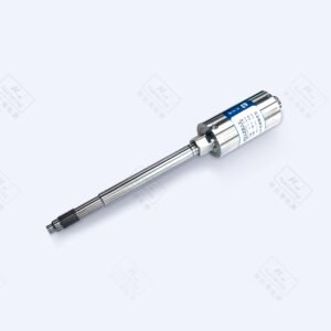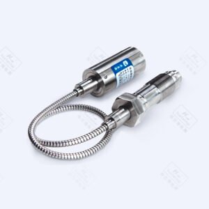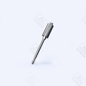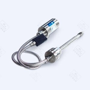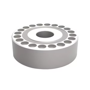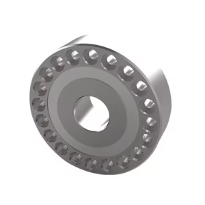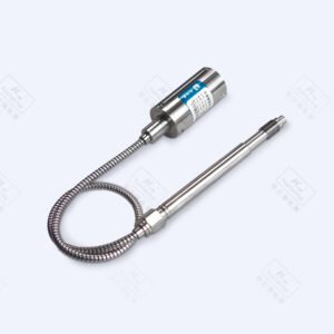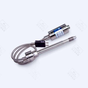


Flush Diaphragm Pressure Sensor with Clamp PC112K
Product Parameters
| Electrical performance parameters | ||
| Pressure range | -100kPa~0~10kPa…10MPa | |
| Pressure reference | Gauge pressure, Absolute pressure, Sealed gauge pressure | |
| Excitation | 1.5mA recommended for constant current;
10V recommended for constant voltage |
|
| Input impedance | Constant current: 2kΩ~5kΩ | |
| Electrical connection | Gold-plated KOVAR pin or silicon soft wire | |
| Compensated temp. | Constant current: 0℃~60℃(≤70kPa); -10℃~70℃(Other ranges) | |
| Operating temp. | -40℃~120℃ | |
| Storage temp. | -40℃~120℃ | |
| Insulation resistance | ≥200MΩ/250VDC | |
| Response time | ≤1ms(Up to 90%FS) | |
| Measuring medium | All the liquids and gases compatible with 316L. | |
| Mechanical vibration | 20g(20~5000HZ) | |
| Shock | 100g/10ms | |
| Durability | 107 pressure cycles | |
| Structural performance parameters | ||
| Diaphragm material | 316L | |
| Housing material | 316L | |
| Filling oil | M20 | |
| Basic parameters | |||||||
| Item | Condition | Min | Nominal | Max | Unit | Note | |
| Non-linearity | -0.3 | ±0.25 | 0.3 | %FS | Note⑴ | ||
| Hysteresis | -0.05 | ±0.03 | 0.05 | %FS | |||
| Repeatability | -0.05 | ±0.03 | 0.05 | %FS | |||
| Zero output | -2 | ±1 | 2 | mV | |||
| Span output | 10kPa
Other ranges |
30
60 |
90
|
150
|
mV | 1.5mA excitation | |
| Zero temp. coefficient | 10kPa
Other ranges |
-2
-1.5 |
±1.5
±0.75 |
2
1.5 |
%FS | Note(2) | |
| Span temp. coefficient | -1.5 | ±0.75 | 1.5 | %FS | Note(2) | ||
| Thermal hysteresis | -0.075 | ±0.05 | 0.075 | %FS | Note(3) | ||
| Long term stability | -0.3 | ±0.2 | 0.3 | %FS/Year | |||
Note:
(1) Calculate according to BFSL least square method.
(2) In the compensated temperature range, refer to 30℃ for 0℃~60℃ and -10℃~70℃.
(3) After passing high and low temperature, return to the reference temperature.


| Pressure range selection | |||||
| Code | Pressure reference | Pressure range | Overpressure | Burst pressure | |
| 20k | G | 0~20kPa | 300%FS | 600%FS | |
| 35k | G | 0~35kPa | 300%FS | 600%FS | |
| 70k | G | 0~70kPa | 300%FS | 600%FS | |
| 100k | G, A | 0~100kPa | 200%FS | 500%FS | |
| 160k | G, A | 0~160kPa | 200%FS | 500%FS | |
| 250k | G, A | 0~250kPa | 200%FS | 500%FS | |
| 400k | G | 0~400kPa | 200%FS | 500%FS | |
| 600k | G | 0~600kPa | 200%FS | 500%FS | |
| 1M | G | 0~1MPa | 200%FS | 500%FS | |
| 1.6M | G, S | 0~1.6MPa | 200%FS | 500%FS | |
| 2.5M | G, S | 0~2.5MPa | 200%FS | 500%FS | |
| 4M | S | 0~4MPa | 200%FS | 400%FS | |
| 6M | S | 0~6MPa | 200%FS | 400%FS | |
| 10M | S | 0~10MPa | 200%FS | 400%FS | |
Note: G: Gauge pressure, A: Absolute pressure, S: Sealed gauge pressure