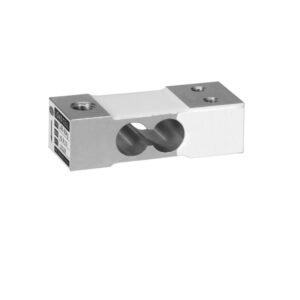


Schenck PWS D1 Platform Load Cell, PWS Type 10 … 700 kg
Application
PWS-type load cells convert propor- tionally the mechanical input varia- ble force into the electrical variable voltage.
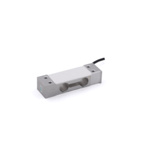
They are ideal for use in platform scales, weighfeeders and bin weighers. The compact design facilitates planning into any given construction.
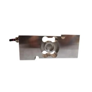
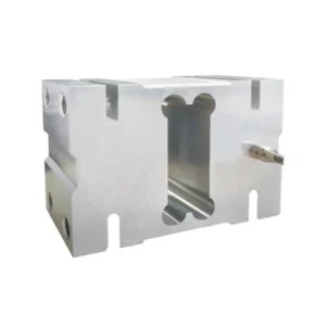
Construction
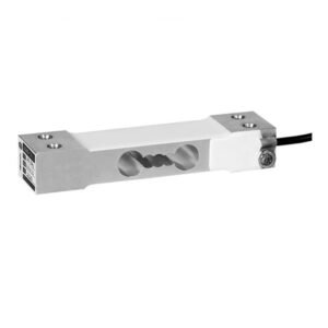
The PWS load cells are produced entirely from stainless steel.
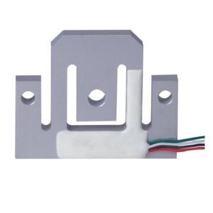
They are connected electrically by a high-quality, 6-wire screened PVC cable.
The six-wire circuitry makes the measuring signal insensitive to differ- ences in lengths of the connection cables.
Functions
High calibration accuracy which provides ideal conditions for the parallel arrangement of load cells
High reproducibility of the measuring signals
Extremely low interference by transverse loads of the meas-ured values
Dimensions [mm]
| Emax = Nominal load | Accuracy class | Part No. | “A” | “B” | “C” | Tightening torque | Nominal measuring route | ATEX Category |
| 10 kg 30 kg 60 kg 100 kg 150 kg 300 kg 500 kg 700 kg 10 kg 30 kg 60 kg 100 kg 150 kg 300 kg 10 kg 30 kg 60 kg 100 kg 150 kg 300 kg 500 kg 700 kg 10 kg 30 kg 60 kg 100 kg 150 kg 300 kg 500 kg 700 kg |
0,05 % 0,05 % 0,05 % 0,05 % 0,05 % 0,05 % 0,05 % 0,05 % C3 C3 C3 C3 C3 C3 0,05 % 0,05 % 0,05 % 0,05 % 0,05 % 0,05 % 0,05 % 0,05 % 0,05 % 0,05 % 0,05 % 0,05 % 0,05 % 0,05 % 0,05 % 0,05 % |
V058895.B01 V058895.B02 V058895.B03 V058895.B04 V058895.B05 V058895.B06 V058895.B07 V058895.B08 V058896.B01 V058896.B02 V058896.B03 V058896.B04 V058896.B05 V058896.B06 V058895.B31 V058895.B32 V058895.B33 V058895.B34 V058895.B35 V058895.B36 V058895.B37 V058895.B38 V058895.B41 V058895.B42 V058895.B43 V058895.B44 V058895.B45 V058895.B46 V058895.B47 V058895.B48 |
8,5 8,5 8,5 8,5 8,5 8,5 10,4 10,4 8,5 8,5 8,5 8,5 8,5 8,5 8,5 8,5 8,5 8,5 8,5 8,5 10,4 10,4 8,5 8,5 8,5 8,5 8,5 8,5 10,4 10,4 |
M8 M8 M8 M8 M8 M8 M10 M10 M8 M8 M8 M8 M8 M8 M8 M8 M8 M8 M8 M8 M10 M10 M8 M8 M8 M8 M8 M8 M10 M10 |
23,8 30,7 30,7 30,7 30,7 30,7 36,5 36,5 23,8 30,7 30,7 30,7 30,7 30,7 23,8 30,7 30,7 30,7 30,7 30,7 36,5 36,5 23,8 30,7 30,7 30,7 30,7 30,7 36,5 36,5 |
32 N m 32 N m 32 N m 32 N m 39 N m 39 N m 79 N m 79 N m 32 N m 32 N m 32 N m 32 N m 39 N m 39 N m 32 N m 32 N m 32 N m 32 N m 39 N m 39 N m 79 N m 79 N m 32 N m 32 N m 32 N m 32 N m 39 N m 39 N m 79 N m 79 N m |
0,30 mm 0,35 mm 0,35 mm 0,45 mm 0,45 mm 0,50 mm 0,50 mm 0,50 mm 0,30 mm 0,35 mm 0,35 mm 0,45 mm 0,45 mm 0,50 mm 0,30 mm 0,35 mm 0,35 mm 0,45 mm 0,45 mm 0,50 mm 0,50 mm 0,50 mm 0,30 mm 0,35 mm 0,35 mm 0,45 mm 0,45 mm 0,50 mm 0,50 mm 0,50 mm |
– – – – – – – – – – – – – – 1D/2G 1D/2G 1D/2G 1D/2G 1D/2G 1D/2G 1D/2G 1D/2G 3GD 3GD 3GD 3GD 3GD 3GD 3GD 3GD 3GD |
Technical Data
| D1 | |
| Nominal characteristic value | 2 ±0,002 mV/V |
| Combined error | 0,05 % *) |
| Sensitivity temperature coefficient, TKc | 0,045 % / 10 K *) |
| Zero signal temperature coefficient, TKo | 0,045 % / 10 K *) |
| Zero signal tolerance | ≤ 2,0 % *) |
| Max. number of increments | – |
| Min. utilization | – |
| Min. load cell increment value ***) | – |
| Nominal temperature | -20 °C … +40 °C |
| Operating temperature Explosion-proof design |
-40 °C … +70 °C -30 °C … +70 °C |
| Storage temperature | -50 °C … +85 °C |
| Max. excitation voltage. | 15 V |
| Input resistance | 390 ±10 Ω |
| Output resistance | 350 ±2 Ω |
| Isolation resistance | > 5000 MΩ |
| Limit load rel. to nominal load | 150 % |
| Breaking load/ nominal load | 300 % |
| Corner load error at 50 % nominal load | 0,05 % / 100 mm |
| Corner load error at 50 % nominal load **) | 0,5 % / 100 mm |
| Material | Stainless steel |
| Protection class Explosion-proof design | IP65 IP67 |
*) Error related to nominal characteristic value
**) at nominal load 500 kg and 700 kg
***) Example: PWS 100 kg
min. utilization Bamin = 42 kg
min. increment value V_min_WZ = 100 kg / 7143 = 14 g (theor. Größe)
i. e., the weighing electronics increment value is the next possible increment = 20 g
Electrical cable: 6 conductor and shield, 5 m long
| Cable | Colour |
|---|---|
| Input voltage + | green |
| Input voltage – | black |
| Measuring signal + | white |
| Measuring signal – | red |
| Sensor cable + | orange |
| Sensor cable – | blue |
| Shield | yellow, pigtail isolated over its entire length |
The connecting cable shield is not connected to the measuring body. Therefore, load cell grounding has to be provided for, e.g. via the connecting structure.
Optional feature ATEX/IECEx approval
| Category | Description / Certification |
|---|---|
| ATEX / IECEx (Gas) | Category 1D/2G and IECEx EPL Da, Gb Gas-Ex: II 2G Ex ia IIC T4 Gb (Zone 1) |
| ATEX / IECEx (Dust) | Dust-Ex: II 1D Ex ia IIIC T125 °C Da, IP67 (Zone 20) |
Warning: The verification of intrinsically safe circuit must be verified. New barriers are provided in particular for new systems. The verifications of intrinsically safe circuit are available for all load cells and barriers.
Load cells marked as intrinsically safe – Ex “i” – are also operated intrinsically safely irrespective of the zone.
| Non intrinsically safe ATEX explosion-proof design | Gas-Ex | II 3G Ex nA IIC T4 Gc | Zone 2 |
| Non intrinsically safe ATEX explosion-proof design | Dust-Ex | II 3D Ex tc IIIC T125 °C Dc, IP67 | Zone 22 |
| IECEx | Gas/Dust | EPL Dc, Gc | — |