


Specifications
| Mechanical parameters | Electrical parameters | ||
| maximum speed | 6000 rpm | Operating Voltage | 10-30Vdc (5Vdc can be customized) |
| Spindle load | Axial 40N, Radial 100N | current consumption | < 300mA (24Vdc) no load |
| impact resistance | 1000m/s²(6ms), equal to 100g | output signal | 12-bit synchronous parallel signal (pure binary, Gray code or Gray remainder) |
| Anti-vibration | 200m/s²(10-2000Hz), equal to 20g | Linear resolution | 1/4096FS, 1/360FS or 1/720FS |
| Allow axial play | ±1.5mm | IP Class | IP65 or IP68 |
| Allow radial runout | ±0.2mm | Repeatability | <2Bit |
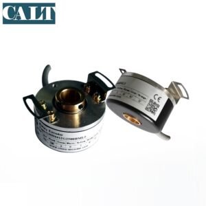
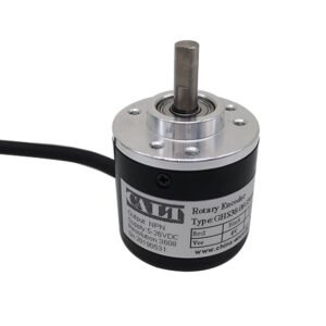
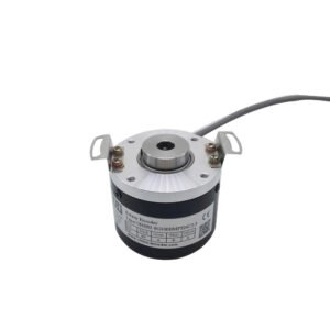
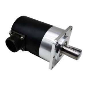
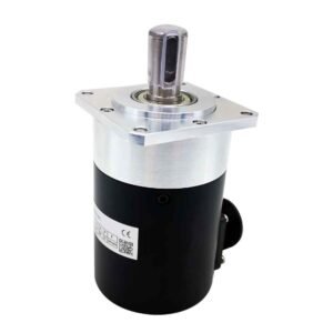
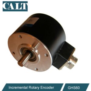
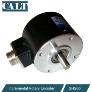
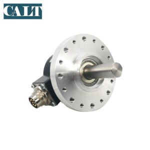
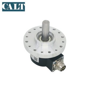
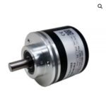
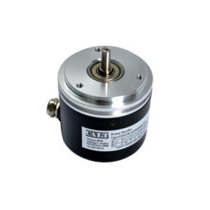
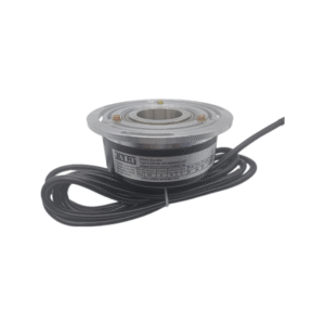
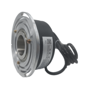
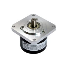
| external structure | 60mm OD, solid shaft, blind hole shaft | Operating temperature | -40℃~85℃ |
| Connection Type | 30 core shielded cable or aviation plug | Storage temperature | -40℃~85℃ |
| reliable and patented
l Strong bearing structure with Safety-Lock TM design, which can provide higher vibration resistance and installation error resistance l IP68 protection grade and wide operating temperature range -40℃…+85℃ l Patented mechanical gear technology, with permanent power-off memory function |
performance optimization
l High precision, data refresh rate of location data ≤ 4us l Direct reading through I/O port l International standard SSI signal format |
Wiring diagram
| Black | 20 | Brown | 28 | Note:
1. For normal use, please short the two wires together 2. Forward and reverse: When connected to 24V+, the counterclockwise data increases 3. Set: connect to 24V + 1 second to set the current value to zero 4. Parallel output maximum 50mA per bit
|
| White | 21 | Orange(white) | 29 | |
| Green | 22 | Green(White) | 210 | |
| Pink | 23 | Brown(White) | 211 | |
| Orange | 24 | Ash | Set Note3 | |
| Purple | 25 | Red | 10-30Vdc | |
| Yellow | 26 | blue/Ash | GND 0V Note1 | |
| Ash(white) | 27 | Blue(White) | Forward and reverse Note 2 |
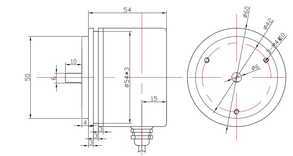
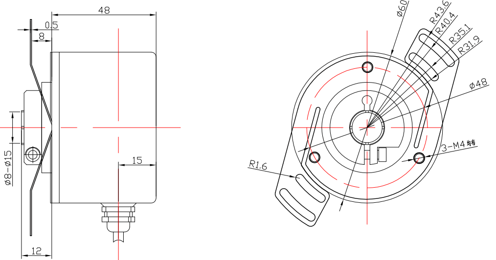
Mechanical dimension drawing
Clamping synchro flange (optional for cable output or plug output)
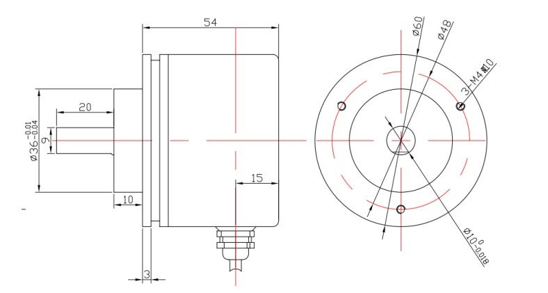
Synchronous flange/servo flange (cable output or plug output optional)
Blind Hole/Half Through Hole Flange (Cable output or plug output optional)
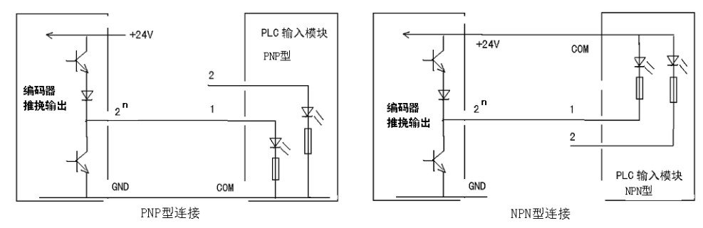
output signal
The output is a parallel push-pull output signal, which is connected to the input module (I/O) of the PLC as shown in the figure below:
-300x300.jpg)