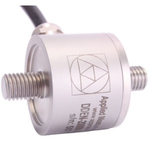


Low Profile Tension and Compression Load Cell | DSCRC
High Accuracy, Low Profile, with a High Frequency Response Applied Measurements DSCRC low profile tension and compression load cell/pancake load cell is manufactured from stainless steel and is suitable for use in weighing and force measurement applications. They can operate in both tension and compression and are commonly used in materials testing and component fatigue testing applications for axial force measurements where a high accuracy, low-profile device is required. The high-frequency response of our DSCRC low profile tension and compression load cell also make them ideal for dynamic force and load measurement applications. The high-speed analogue SGA amplifier is an ideal complement to the DSCRC, offering a conditioned signal output of 4-20mA, ±5Vdc or ±10Vdc with a bandwidth of up to 6kHz. As with all our load cells, the DSCRC low profile tension and compression load cell design can be modified to suit your exact requirements, with alternative threads, custom dimensions and customer-specific capacities. If you require a rated capacity greater than 0-2kN, the DSCC low profile load cell covers forces from 0-5kN up to 0-1000kN as standard.
Technical Specifications
| Rated Capacity (RC) | N | 0-200, 0-500, 0-1000, 0-2000 |
|---|---|---|
| Operating Modes | Tension/Compression / Tension & Compression | |
| Sensitivity (RO) | mV/V | 2.0 nominal (1.0 on fatigue-rated versions) |
| Zero Balance/Offset | ±%/Rated Output | <5.0 |
| Output Symmetry (tension vs. compression) | %/Rated Output | <0.5 typical |
| Non-Linearity | ±%/Rated Output (BFSL) | <0.10 |
| Hysteresis | %/Rated Output | <0.08 |
| Repeatability | ±%/Applied Load | <0.03 |
| Temperature Effect on Zero | ±%/Rated Capacity/ ˚C | <0.005 |
| Temperature Effect on Sensitivity | ±%/Applied Load/ ˚C | <0.005 |
| Input Resistance | Ohms | 375 nominal |
| Output Resistance | Ohms | 350 nominal |
| Insulation Resistance | Megohms | >5000 @ 50Vdc |
| Excitation Voltage | Volts AC or DC | 10 recommended (2-15 acceptable) |
| Operating Temperature Range | ˚C | -20 to +80 |
| Compensated Temperature Range | ˚C | 0 to +60 |
| Storage Temperature Range | ˚C | -20 to +80 |
| Safe Overload | % of Rated Capacity | 150 |
| Ultimate Overload | % of Rated Capacity | 300 |
| Deflection @ Rated Capacity | mm | <0.4 nominal |
| Fundamental Resonant Frequency* | See table | |
| IP Rating (Environmental Protection) | IP65 (2000N version) / IP52 (1000N and below) | |
| Weight (excluding cable) | kg | 0.75 (1.65 with base) |
| Fatigue Life | 108 cycles typical (109 cycles on fatigue-rated version) | |
| Cable Length (as standard) | metres | 3 |
| Cable Type | 4 core screened, PUR sheath, Ø5 | |
| Electrical Connections | 6 Pin Bayonet Lock Connector (MIL-C-26482-10-6P) + mating cable assembly | |
| Construction Material | Stainless Steel | |
| Resolution | 1 part in 250,000 (with appropriate instrumentation) | |
| *The resonant frequency is calculated with the body of the load cell attached to a large plate, ensuring that only the sensing element oscillates: This is vital to achieve the highest natural frequency and subsequent frequency response. | ||
Product Dimensions
|
Capacity (N)
|
ØD
|
H
|
G
|
K
|
T
|
ØP
|
R
|
Natural Frequency (kHz) |
|---|---|---|---|---|---|---|---|---|
| 200 |
76
|
25
|
60
|
6 off Ø7
|
M10 x 1.0
|
11
|
7
|
1.5 |
| 500 |
76
|
25
|
60
|
6 off Ø7
|
M10 x 1.0
|
11
|
7
|
2.2 |
| 1000 | 76 | 25 | 60 | 6 off Ø7 | M10x1.0 | 11 | 7 | 3 |
| 2000 | 76 | 25 | 60 | 6 off Ø7 | M10x1.0 | 11 | 7 | 4 |
All dimensions are in mm
Wiring Details
| Wire | Designation |
|---|---|
| Red | +ve excitation |
| Blue | -ve excitation |
| Green | +ve signal (compression) |
| Yellow | -ve signal |
| Screen | To ground – not connected to load cell body |
Ordering Codes & Options
| Core Product | Capacity (inc Engineering Units) | Cable Length (m) | Specials Code | Example Result |
|---|---|---|---|---|
| DSCRC | 200N | 003 | 000 | DSCRC-200N-003-000 |
| DSCRC | 500N | 003 | 000 | DSCRC-500N-003-000 |
| DSCRC | 1000N | 003 | 000 | DSCRC-1000N-003-000 |
| DSCRC | 2000N | 003 | 000 | DSCRC-2000N-003-000 |
Mounting And Installation Accessories
Load Buttons and Rod End Bearings
Designed to align forces through the principal axis of the load cell thus reducing the effects of extraneous forces, hence offering improved performance from the cell. Load buttons are used where compressive forces are applied. Rod End Bearings are used where tensile forces are being applied.
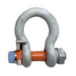
Load Buttons for Compressive Use
| THREAD T | M10x 1.0 |
|---|---|
| D | 16 |
| H | 6 |
| L | 10 |
| R | 150 |
Rod End Bearings for Tension Use
Maintenance-free rod ends are a complete units made up of a housing with both an integral shank (with an internal or external thread) and a maintenance-free spherical plain bearing, located within the housing. Key Features:
- Supports radial loads in a tensile or compressive direction.
- Suitable for unilateral loads – can support alternating loads and alternating loads in combination with bearing GE..UK-2RS, please consult sales.
- Are maintenance-free.
- Hard chromium/PTFE composite sliding contact surfaces.
- Enables compact adjacent construction thanks to its thin-walled design of the eye housing.
Series GAXSW..MS
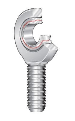
Rod ends with male thread made from heat-treated steel, nickel plated with PTFE liner, maintenance free. Preloaded bearing.
| Specifications | |
|---|---|
| Housing | Heat-treated steel to 42CrMo4, Aisi 4140, forged, polished, nickel plated with high polish finish. |
| Insert | Stainless Steel to 1.4571, Aisi 316Ti with PTFE liner bonded to inner surface. |
| Ball | Bearing steel to 100Cr6, Aisi 52100, hardened, ground, polished, hard chrome plated on the running surface. |
| Clearance | Preloaded, zero tollerance. |
| On Request | With left hand thread, threaded bolt and further sizes are available |
| Load Cell | Ordering Code | DH7 | B | M | A | F | L | O | G | GL | Static radial load C0 kN | Dynamic radial load C0 kN | Torque Ndm | α | weight gr |
|---|---|---|---|---|---|---|---|---|---|---|---|---|---|---|---|
| DSCRC 200N to 2000N | GAXSW 10×1 MS | 10 | 14 | 10.5 | 28 | 48 | 62 | 12.9 | M 10×1 | 29 | 31.4 | 28.1 | 6-16 | 13° | 56 |