


BRG-ZX001 Pin Load Cell
Description
Product Description
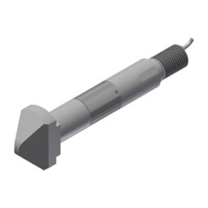
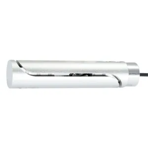
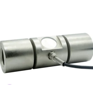
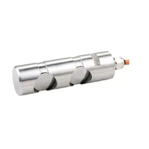
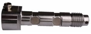
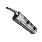
Load pins are designed to be installed directly into machines or assemblies, replacing existing non-instrumented shafts or pins. They act as a normal component of the assembly while measuring the forces acting on them. The strain gauges on the load pin detect the deformation caused by the applied force, which is then converted into an electrical signal proportional to the force.

Technical Parameters
| Rated quantitative schedule | T | 0-100 |
| Output sensitivity | mV/V | 1.0±0.05 |
| Zero point output | %F.S. | ±2 |
| Non-linear | %F.S. | 0.5 |
| lag | %F.S. | 0.5 |
| Repeatability | %F.S. | 0.5 |
| Creep (30 min) | %F.S. | 0.5 |
| Temperature sensitivity drift | %F.S./10℃ | 0.05 |
| Zero temperature drift | %F.S./10℃ | 0.05 |
| Response frequency | Hz | 1k |
| Material | 42CrMoA | |
| impedance | Ω | 350 |
| Insulation resistance | MΩ/100V DC | ≥5000 |
| Use voltage | V | 5-15 |
| Operating temperature range | ℃ | -20-80 |
| Safety overload | %R.C. | 150 |
| Extreme overload | %R.C. | 300 |
| Cable line specifications | m | Φ5*3m |
| Cable limit pull force | N | 98 |
| TEDS | selectable |
Dimension (mm)

| Range (T) | A | B | C | D | E | F | G | H | K | M |
| 2,3,5 | 50 | 180 | 66 | 27 | 4.5 | 6.5 | 32 | 7 | 9 | 3 |
| 7,10 | 60 | 190 | 96 | 14 | 10 | 9 | 33 | 9 | 9 | 5 |
| 10,15 | 65 | 210 | 116 | 14 | 10 | 9 | 32 | 9 | 8 | 5 |
| 20,30 | 80 | 225 | 109 | 20 | 12 | 11 | 40 | 10 | 8 | 6 |
| 40,50,100 | 120 | 275 | 153 | 25 | 14 | 13 | 51 | 15 | 12 | 6 |
Force Diagram


How Does a pin load cell work ?
A load pin, also known as a clevis pin or dynamometric axle, is a type of load cell used for measuring force or weight in various applications. It is a rod-shaped sensor with strain gauges bonded on its surface, typically at 45° angles with respect to the axis.